
Blog
Inventor vs PowerShape for Mould Design
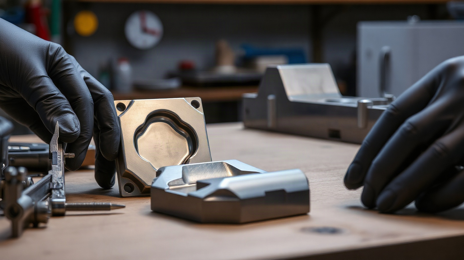
Choosing between Inventor and PowerShape for mould design is less about counting features and more about understanding the geometry your shop receives and the way engineers must change it. A standardised mould base with replaceable inserts presents a different CAD problem from a scanned component, a freeform automotive panel or a die containing difficult imported surfaces.
Autodesk Inventor Professional is clearly positioned around parametric mechanical design: 3D parts, assemblies and technical documentation developed from linked sketches, dimensions, constraints and features. Autodesk PowerShape is a separate Autodesk design product that many toolmaking teams evaluate for complex mould, die and surface-driven work. The correct choice depends on whether design intent, complex geometry, production repeatability or imported data is the main concern.
Different design challenges in mould and die work
A mould-making or toolmaking shop normally deals with several types of CAD information at the same time. The tool may include a standard base, plates, guide systems, inserts, cooling components, slides, lifters, electrodes and machined cavities. Some components are controlled by dimensions and relationships; others are derived from a customer part or a supplied surface model.
These tasks create four practical questions:
- Is the geometry mechanical or freeform? Plates, holes, bolts, spacers and many insert systems are easier to control as dimensioned features. Product surfaces and repaired imported models may require a different approach.
- Will the design change repeatedly? A family of moulds with different cavity sizes benefits from linked dimensions and reusable design logic.
- How clean is the source model? A native, well-structured model is easier to edit than a model with gaps, unrelated surfaces or incomplete design history.
- Where does CAM begin? The CAD model must be suitable for toolpath preparation, but CAD design and CAM programming are not automatically the same task.
For this reason, a broad feature checklist can be misleading. A shop producing mostly standardised tools may need predictable parametric change more than specialised surface manipulation. A shop machining complex cavities may place greater value on controlling difficult geometry and preparing a reliable handover to its CAM process.
Inventor Professional: a parametric mechanical design approach
Inventor Professional provides a dedicated environment for building parametric 3D parts, detailed assemblies and technical documentation. Its central strength for mould design is the relationship between design dimensions, constraints and features. When an engineer changes a hole diameter, wall thickness or component length, the model can update through those relationships instead of requiring every affected element to be edited manually.
Where Inventor fits well
Inventor mould design is a strong fit when the tool is built from controlled mechanical components. Examples include mould plates, mounting arrangements, standard inserts, support structures, fixtures and assemblies that must be documented for manufacture or customer approval.
A typical workflow might begin with a part and assembly structure for the mould base. The designer defines plate thicknesses, hole positions and insert locations, then creates drawings and documentation from the 3D model. If the product requires a revision, the designer can change a controlled parameter and inspect how the related parts and assembly respond.
This approach is particularly useful for shops that:
- build recurring tool families with known design rules;
- need clear assemblies and production documentation;
- expect frequent engineering changes;
- coordinate several mechanical components rather than only a cavity surface;
- want design intent to remain understandable to another engineer.
Limits to consider with Inventor
Parametric mechanical modelling does not remove every difficulty in mould work. A customer model may contain imported or complex surfaces that do not behave like native Inventor features. Repairing, redesigning or heavily modifying such geometry can take more planning than changing a fully constrained mechanical part.
Inventor is also not automatically a complete CAM solution for every shop. A team responsible for CNC programming, simultaneous 5-axis milling, electrode manufacture or detailed toolpath verification should confirm which CAM software and integrations are required. The CAD model can support manufacturing, but the design licence should not be treated as a substitute for a complete machining workflow.
PowerShape: evaluate it around complex tool geometry
PowerShape should be evaluated differently from Inventor. Instead of asking whether it can replace a general mechanical design system, a shop should ask whether it fits the way it receives, edits and prepares complex mould and die geometry.
This is especially important when the starting point is not a clean, native parametric model. Toolmakers may receive customer data containing imported surfaces, complex curvature or geometry that must be adapted before it can be used for a cavity, core, insert or machining strategy. In that environment, the practical question is how efficiently the software can control the required shapes and pass usable data to the next stage.
Because the available product description for the PowerShape listing does not specify a complete feature matrix, confirm the exact current capabilities before purchase. Ask Autodesk or your technical reseller to demonstrate the operations that matter to your shop: imported-model repair, surface editing, solid and surface interoperability, split and parting workflows, complex cavity preparation, reverse-engineered data and the handover to your CAM system.
Where PowerShape may fit better
PowerShape is the candidate to investigate when the dominant problem is difficult geometry rather than a plate-and-component assembly. This may include moulds with complex product surfaces, customised dies, imported customer data or reverse-engineering work based on measured physical parts.
For a CNC-focused shop, the evaluation should use a real project rather than a generic demonstration. Provide a representative model with the gaps, blends, parting areas and machining constraints that normally consume time. Then assess how the software handles the complete path from received geometry to a clean design suitable for CAM programming.
Do not assume that a software name alone guarantees a specific 5-axis workflow. Confirm whether the required 5-axis toolpath creation, collision checking, simulation and post-processing are provided by PowerShape, by a separate Autodesk product or by another CAM system in your production environment.
Inventor vs PowerShape for mould design
| Decision area | Inventor Professional | PowerShape |
|---|---|---|
| Primary design logic | Parametric mechanical design using sketches, dimensions, constraints and features. | Evaluate it primarily for complex, imported or surface-driven tool geometry. |
| Standard mould components | Strong fit for plates, assemblies, inserts and dimension-controlled components. | Confirm whether it offers the mechanical assembly and documentation workflow your shop needs. |
| Design changes | Useful when dimensions and relationships must update through the model. | Assess how changes to complex surfaces and imported data are controlled in the required workflow. |
| Complex cavity and die geometry | Possible fit when the geometry can be managed effectively in a mechanical parametric model. | Candidate for investigation when complex or imported geometry is the central problem. |
| Reverse engineering | Confirm the required scan, mesh and surface workflow before relying on it. | Request a demonstration using the shop’s actual measured or imported data. |
| CAM and 5-axis machining | Do not assume the CAD licence alone provides the complete CAM workflow. | Verify the exact CAM products, integrations and post-processing required. |
| Documentation | Well suited to assemblies and technical documentation generated from the design model. | Confirm drawing and documentation requirements for the intended production process. |
Choosing software for standardised versus custom tools
Choose Inventor Professional first when your main business is the repeatable design of mechanical mould assemblies. This is the more direct choice when your engineers need controlled dimensions, editable design intent, detailed assemblies and technical documentation. It is also a sensible option when several people must understand and revise the same design without reconstructing the reasoning behind it.
For example, a shop making similar injection mould bases for different component sizes could use a structured Inventor model as the starting point. Plate dimensions, insert locations and component lengths can be treated as controlled design information. The benefit is not simply drawing the mould once; it is making later revisions more predictable.
Investigate PowerShape first when every project begins with difficult product geometry or when the main commercial value of the shop is complex surface and tool preparation. This is more likely in custom mould making, die work, model-based manufacturing and reverse-engineering projects. Use a production sample to test the complete workflow, not only the ability to open a file.
For a shop doing both types of work, the answer may not be either-or. One product can manage the structured mechanical assembly while another handles the geometry that is difficult to create or edit in a conventional parametric workflow. The important point is to define ownership of the master model, file formats, revision control and the handover to CAM.

When a shop may use both
A combined workflow can make sense when mould design contains two distinct layers. The first layer is the product-derived geometry: cavity surfaces, core surfaces, inserts and other shapes driven by the customer part. The second layer is the mechanical tool: plates, supports, fasteners, cooling-related components and the assembly that holds everything together.
Before adopting both products, agree on a controlled process:
- Define the source of truth. Decide which system owns the cavity, the mechanical assembly and the final manufacturing data.
- Test translation. Use a real project to check whether geometry, tolerances, references and revision information survive the exchange.
- Separate design from CAM responsibility. Identify who prepares surfaces, who creates toolpaths and who approves the final NC output.
- Document revisions. A change to the customer part must be traceable through the cavity, inserts, plates and machining data.
- Train for the actual role. Designers working on assemblies need a different workflow from specialists preparing complex surfaces for machining.
A two-product workflow adds licences, training and data-management overhead. It is justified only when the geometry problem is substantial enough to offset that complexity. For a smaller shop with mostly standard mechanical tools, starting with Inventor Professional may be easier to manage. For a specialist shop whose projects are dominated by complex imported shapes, a focused PowerShape evaluation is more important than trying to force every task into a general parametric workflow.
Licence and deployment points
Both Autodesk Inventor Professional and Autodesk PowerShape are Windows products listed with one-device licensing options and one- or three-year key terms. The Autodesk licence is assigned to an Autodesk account. If an account does not already exist, the account setup uses the customer’s name and email address.
Language availability differs between the products, so check the product page and the needs of your design team before ordering. Also confirm that your chosen product matches the workstation, data-exchange and CAM environment used by the shop.
Συχνές ερωτήσεις
Is Inventor or PowerShape better for mould design?
Neither is universally better. Inventor is the clearer fit for parametric mechanical mould assemblies and documentation. PowerShape should be evaluated when complex, imported or surface-driven geometry is the main challenge.
Can Inventor be used for CNC mould production?
Inventor can provide the mechanical 3D design and documentation, but do not assume that it includes every CAM function needed for CNC or 5-axis machining. Confirm the separate CAM workflow required by your shop.
Is PowerShape a complete replacement for Inventor?
Not automatically. They should be compared by workflow rather than by brand. A shop needing structured mechanical assemblies may still require Inventor, while a shop focused on complex tool geometry may prioritise PowerShape or use both.
Which software is better for reverse engineering?
Base the decision on a demonstration with your own scan, mesh or measured data. Confirm import, repair, surface creation, editing, revision control and the handover to CAM before choosing.
Where can I buy a genuine licence?
Genuine Autodesk Inventor Professional and Autodesk PowerShape licences are available from KEYFORREST with instant electronic delivery. See the current product page for the available term, language and licence details.

Σχετικά με τον Marios Chaidousis
Σχετικές δημοσιεύσεις

Windows 11 for CNC Workstations: Migration Checklist
-
Δημοσιεύτηκε από Marios Chaidousis
A Windows 11 migration can affect CAM software, post-processors, drivers, machine settings and production schedules. Use this practical checklist to test compatibility, protect manufacturing data and move CNC workstations in controlled stages.

From Scan to Toolpath: A CNC Reverse-Engineering Workflow
-
Δημοσιεύτηκε από Marios Chaidousis
A reliable reverse engineering CNC workflow does more than convert a scan into a surface model. It connects measurement, geometry repair, machining strategy, verification and revision control so that an inherited or physical part can become repeatable CNC output.

PowerShape for Mould Design: Prepare Better Tooling Geometry
-
Δημοσιεύτηκε από Marios Chaidousis
Mould and die work often starts with incomplete, imported or difficult geometry rather than a clean part model. This guide explains where PowerShape for mould design fits into geometry preparation, surface work and CAM-ready inspection.

PowerShape vs PowerMill: Which Comes First?
-
Δημοσιεύτηκε από Marios Chaidousis
PowerShape and PowerMill are not interchangeable alternatives. PowerShape belongs at the design and geometry-preparation stage, while PowerMill is used to program CNC machining operations.

Best CAM Software for CNC Job Shops: A Practical Guide
-
Δημοσιεύτηκε από Marios Chaidousis
The best CAM software for CNC machining depends on the parts you make, the machines you run and the experience of your programmers. This practical guide compares PowerMill and Autodesk’s Product Design & Manufacturing Collection by real job-shop workflows.
PowerMill for 5-Axis CNC Machining
-
Δημοσιεύτηκε από Marios Chaidousis
PowerMill is CAM software for manufacturers programming demanding 3-axis and multi-axis CNC work. This guide explains where it fits in 5-axis machining, toolmaking, mould making and complex-surface production.