
Blog
PowerMill for 5-Axis CNC Machining
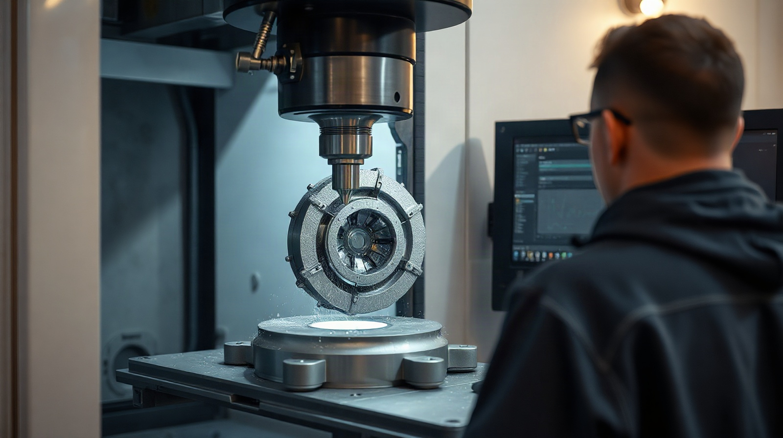
PowerMill for 5-axis machining is aimed at CNC programming teams that need more control over tool movement, surface finish and machining time than a basic CAM workflow can provide. It is particularly relevant when a part contains deep cavities, steep walls, complex surfaces or areas that are difficult to reach with a fixed tool axis.
For toolmaking and mould-making shops, the challenge is rarely just generating a cutter path. Programmers must decide how to orient the tool, how to approach a surface, where to split operations and how to keep the process practical for the available CNC equipment. Autodesk PowerMill provides a specialist CAM environment for these decisions on Windows computers, with support for 3-axis and multi-axis CNC machining.
This article explains how PowerMill fits into demanding 5-axis production, what it can and cannot replace, and what to check before choosing a licence.
Why 5-axis work needs specialised CAM planning
In 3-axis machining, the cutting tool usually moves along three linear axes while its orientation stays fixed. This can be effective for relatively accessible geometry, but it becomes less efficient when the tool must reach around a wall, follow a compound surface or machine a deep feature without excessive tool extension.
With 5-axis machining, the tool position and orientation can change during an operation. That creates more possibilities, but also more programming decisions. A useful toolpath must account for the part geometry, the cutting direction, the holder and tool assembly, the machine configuration and the intended finish. Poorly planned motion can lead to unnecessary retracts, unfavourable tool angles, uneven marks or a process that is difficult to run on the shop floor.
These issues are common in:
- Injection mould cavities and core components with steep or curved surfaces.
- Dies with deep pockets, narrow access areas and complex transitions.
- Tooling inserts that require controlled finishing from several orientations.
- Complex components where a fixed-axis approach leaves uncut areas.
- Parts requiring fewer setups or better access to difficult surfaces.
PowerMill is designed for this type of work. Its purpose is to help machining teams convert detailed digital models into controlled toolpaths while reducing manual programming effort for intricate geometry. It does not remove the need for an experienced programmer: the user still has to select appropriate strategies, cutting tools, feeds, speeds, stock conditions and machine settings.
Programming complex surfaces with PowerMill
Toolmaking and mould making often involve surfaces that are visually smooth but technically difficult to machine. A cavity may combine shallow areas, steep walls, fillets and narrow channels. A die may include a deep form that cannot be reached efficiently with a short, rigid tool. The CAM system must turn this geometry into operations that are both accurate and practical.
PowerMill CAM software is suited to programming operations where tool movement needs close control. The programmer can organise the work around the actual geometry and decide how the cutter approaches different regions. Instead of relying on one general-purpose operation, the process can be divided into stages such as roughing, rest machining, semi-finishing and finishing, depending on the part and the shop’s established method.
A typical complex-surface workflow may look like this:
- Prepare the model. Check the CAD data, identify machining boundaries and confirm which surfaces require material removal or protection.
- Plan stock removal. Use a roughing approach that removes material efficiently while leaving a controlled allowance for later operations.
- Separate geometry by machining behaviour. Deep areas, steep walls, shallow surfaces and narrow features may need different strategies and tool orientations.
- Control the tool axis. Choose an orientation that supports access, cutting conditions and surface quality rather than allowing the tool to move unpredictably.
- Refine remaining material. After larger tools have removed accessible material, use smaller tools or different orientations for areas that remain.
- Review the result. Inspect tool motion, transitions, possible collisions and the expected finish before sending output to the CNC process.
The exact sequence depends on the machine, tooling, material and required tolerance. PowerMill helps create the toolpath, but the final production method still belongs to the machining team.
5-axis toolpaths for moulds, dies and tooling
For mould and die work, 5-axis programming is valuable when the tool must maintain a more suitable relationship with the surface. Tilting the tool can improve access to a cavity, reduce the need for long tool extensions or avoid cutting with an unfavourable part of the cutter. It can also support a more consistent finishing approach across complex regions.
However, using five axes does not automatically make every operation better. A 3-axis operation may be simpler and more predictable for a broad, accessible surface. A 5-axis operation may be preferable for a deep wall, an undercut area that the machine can reach, or a region where tool orientation has a significant effect on finish and stability.
PowerMill for 5-axis machining therefore fits best as a planning and control tool. It gives the programmer a way to choose where simultaneous or indexed multi-axis motion is appropriate rather than treating 5-axis machining as an automatic setting applied to the entire part.
For a mould-making shop, a practical division might be:
| Part area or task | Possible CAM approach | What the programmer should check |
|---|---|---|
| Large open cavity surfaces | Efficient roughing followed by surface finishing | Stock allowance, step-over, cutting direction and finish consistency |
| Steep cavity walls | Finishing with a controlled tool axis | Tool access, holder clearance and marks at transitions |
| Deep pockets or narrow features | Smaller tools and carefully planned orientations | Tool length, rigidity, remaining material and safe retracts |
| Fillets and blended transitions | Dedicated finishing passes or a separate operation | Surface continuity, cusp height and local accessibility |
| Areas with limited access | Indexed or multi-axis machining where suitable | Machine travel, rotary-axis limits and actual workholding |
This approach can reduce the amount of manual editing needed for complicated toolpaths, but it should always be validated against the real machine and tooling setup.
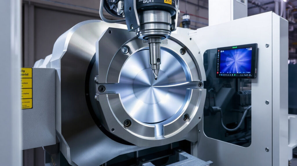
Collision avoidance and machine-aware verification
In multi-axis machining, avoiding a collision involves more than checking whether the cutter touches the finished part. The tool holder, spindle nose, fixture, stock and machine movement may all matter. A toolpath that appears acceptable from the model view may not be suitable for the actual machine configuration.
Before buying or deploying PowerMill, a shop should establish how it will verify:
- Clearance between the cutter assembly and the part.
- Clearance between the holder, spindle and surrounding geometry.
- Fixture and workholding access.
- Rotary-axis movement and travel limits.
- Rapid moves, linking moves and retract behaviour.
- The relationship between the calculated toolpath and the CNC machine’s post-processed output.
PowerMill is intended to provide greater control over tool movement, but CAM verification is not a substitute for responsible machine setup. The post processor, machine kinematics, tool data, work offset, workholding and operator checks must all be correct. A programmer should confirm the workflow with the relevant machine and post-processing configuration before relying on it for production.
For a new 5-axis process, begin with a representative component rather than a simple test block. A mould insert or tooling component with a deep feature, steep wall and blended surface will reveal whether the chosen workflow gives the required access, finish and cycle-time behaviour.
PowerMill workflows for toolmaking and mould making
PowerMill can sit between the design model and the CNC machine in a wider manufacturing workflow. The design may originate in a CAD system, while measurement or scanning equipment may be used when an existing physical component has to be recreated. PowerMill then works with the available digital geometry to plan machining operations.
It is important to define this boundary clearly. PowerMill is CAM software; it does not replace a CAD system for designing a mould, and it does not by itself perform the complete reverse-engineering process from a physical part. If reverse engineering is part of the shop’s service, the team will still need suitable measurement, scanning, inspection or CAD tools to produce usable geometry. PowerMill can then be considered for programming that geometry.
A typical tooling workflow can include:
- Design handover: receive and inspect the model, including the surfaces and boundaries that control machining.
- Manufacturing planning: decide the workholding, setups, tools and order of roughing and finishing operations.
- Toolpath creation: generate operations suited to accessible, steep, deep and complex-surface areas.
- Multi-axis refinement: introduce appropriate tool-axis changes where they improve access or control.
- Verification: review the complete process against the machine and physical setup.
- CNC preparation: produce the required machine output through the shop’s established post-processing workflow.
- Inspection and finishing: measure the machined component and apply any manual finishing or correction required by the specification.
The benefit is not simply fewer clicks in CAM programming. A well-planned process can make difficult geometry more repeatable and easier to hand over between programmers. It can also give the shop a clearer method for handling similar moulds, dies and inserts in the future.
What PowerMill does and does not do
| PowerMill is suitable for | PowerMill is not a replacement for |
|---|---|
| Programming demanding 3-axis and multi-axis CNC machining | Physical machine setup and operator responsibility |
| Planning toolpaths for complex surfaces, deep cavities and steep walls | A CAD system for designing the complete mould or die |
| Giving programmers greater control over tool movement and machining operations | Correct cutting-tool selection, feeds, speeds and workholding decisions |
| Supporting a structured workflow for tooling and difficult components | Inspection equipment or a complete reverse-engineering system |
| Reducing some manual programming effort for intricate geometry | A guarantee that every toolpath is safe without verification |
What to check before buying PowerMill
Start with the parts your shop actually produces. Collect examples of mould cavities, dies, inserts or other complex components that currently require extensive manual editing. Note which problems matter most: inaccessible surfaces, long tools, inconsistent finish, repeated setups, excessive linking moves or difficult multi-axis programming.
Then check the following points:
- Machine scope: confirm that the intended workflow matches your 3-axis or multi-axis CNC equipment.
- Geometry: test representative complex surfaces rather than evaluating only simple prismatic parts.
- Tooling: verify that the planned tools, holders and extensions can be represented and used safely in the process.
- Post-processing: clarify how output for each machine will be configured and validated.
- Team skills: identify who will create standards, templates and verification procedures.
- Data workflow: confirm how CAD models, revisions, stock information and inspection results move through the shop.
- Licence requirements: PowerMill is a Windows product, and the available product licence options are for one or three years and one device.
PowerMill supports English, German, French, Italian, Spanish, Polish, Russian, Portuguese (Brazil), Japanese and Chinese (Simplified). The Autodesk licence is assigned to an Autodesk account. If the user does not already have one, an account can be created using the name and email address supplied for the order.
Which shops should consider PowerMill?
PowerMill is a strong candidate for shops that regularly machine complex tooling and need a dedicated CAM workflow for difficult surfaces and multi-axis work. It is especially relevant when standard machining strategies produce too much manual adjustment or do not provide enough control over tool orientation and movement.
A simpler CAM solution may be sufficient for mainly 2.5D work, straightforward 3-axis parts or occasional basic milling. Conversely, a shop with demanding mould, die, aerospace, automotive or specialist tooling work should evaluate PowerMill using its real components, machines and post-processing requirements.
Genuine Autodesk PowerMill licences are available from KEYFORREST with instant electronic delivery. Select the licence term and confirm the current product details on the product page before ordering.
Preguntas frecuentes
Is PowerMill suitable for 5-axis CNC machining?
Yes. PowerMill is designed for demanding 3-axis and multi-axis CNC programming, including work where changing the tool orientation helps reach complex surfaces, deep cavities and steep walls. The exact result depends on the machine, tooling and post-processing setup.
Can PowerMill be used for mould and die making?
Yes. Its focus on controlled tool movement and intricate geometry makes it relevant to mould cavities, dies, tooling inserts and other components with complex surfaces. Shops should test their own representative parts before standardising the workflow.
Does PowerMill replace CAD software?
No. PowerMill is CAM software for creating machining operations from digital geometry. A separate CAD system may still be needed to design or modify moulds, dies and other components.
Can PowerMill perform reverse engineering?
PowerMill does not replace the complete scanning, measurement and CAD reconstruction process. A shop may use other tools to create usable digital geometry, then use PowerMill to program the machining of that geometry.
What type of licence is available?
The listed Autodesk PowerMill options are for one or three years and one device. The licence is assigned to an Autodesk account, and the product runs on Windows. Check the current product page for the available option and price.

Acerca de Marios Chaidousis
Artículos relacionados
Windows 11 for CNC Workstations: Migration Checklist
-
Publicado por Marios Chaidousis
A Windows 11 migration can affect CAM software, post-processors, drivers, machine settings and production schedules. Use this practical checklist to test compatibility, protect manufacturing data and move CNC workstations in controlled stages.
From Scan to Toolpath: A CNC Reverse-Engineering Workflow
-
Publicado por Marios Chaidousis
A reliable reverse engineering CNC workflow does more than convert a scan into a surface model. It connects measurement, geometry repair, machining strategy, verification and revision control so that an inherited or physical part can become repeatable CNC output.
Inventor vs PowerShape for Mould Design
-
Publicado por Marios Chaidousis
Inventor and PowerShape suit different mould and die workflows. This comparison focuses on parametric mechanical design, complex geometry, manufacturing handover and the situations where a shop may use both.
PowerShape for Mould Design: Prepare Better Tooling Geometry
-
Publicado por Marios Chaidousis
Mould and die work often starts with incomplete, imported or difficult geometry rather than a clean part model. This guide explains where PowerShape for mould design fits into geometry preparation, surface work and CAM-ready inspection.
PowerShape vs PowerMill: Which Comes First?
-
Publicado por Marios Chaidousis
PowerShape and PowerMill are not interchangeable alternatives. PowerShape belongs at the design and geometry-preparation stage, while PowerMill is used to program CNC machining operations.

Best CAM Software for CNC Job Shops: A Practical Guide
-
Publicado por Marios Chaidousis
The best CAM software for CNC machining depends on the parts you make, the machines you run and the experience of your programmers. This practical guide compares PowerMill and Autodesk’s Product Design & Manufacturing Collection by real job-shop workflows.