
Blog
ReCap Civil 3D Point Cloud Workflow for Terrain Models
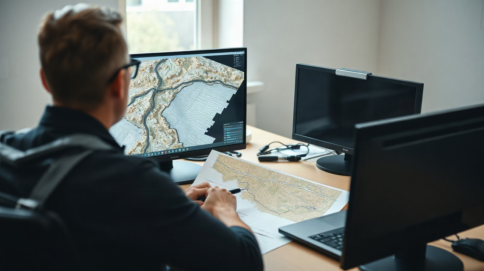
Laser scans and other reality-capture surveys can record roads, rail corridors, bridges, embankments, channels, buildings and existing utilities in considerable detail. The challenge is turning that dense survey information into an engineering model that is suitable for alignments, earthworks, pipe networks and tender documentation.
A reliable ReCap Civil 3D point cloud workflow separates two tasks. ReCap Pro is used to prepare, organise and review the scan data. Civil 3D is then used to create a terrain model and connect it with civil design objects, profiles, corridors, pipe networks and drawings. The point cloud remains valuable evidence, but it should not automatically be treated as a finished ground surface.
When point clouds are useful for infrastructure surveys
Point clouds are particularly useful when the existing environment is irregular, difficult to access or too detailed to capture efficiently with a small number of conventional survey points. A scan can help a project team understand the condition and geometry of:
- road pavements, kerbs, verges, barriers and retaining walls;
- rail tracks, platforms, cuttings, embankments and station structures;
- bridges, tunnels, culverts and other structures;
- rivers, drainage channels, flood defences and water infrastructure;
- construction sites and corridors where existing levels must be compared with design intent.
For preliminary design, the cloud can reveal constraints before an alignment or grading solution is fixed. An engineer can inspect clearance, slopes, tie-in locations and the relationship between the route and existing structures. For earthworks, a suitable terrain surface can support cut-and-fill studies and corridor design. For utilities, the survey may help locate visible covers, chambers, channels and surface features that influence pipe routes.
However, scan density is not the same as survey reliability. A cloud may contain vegetation, vehicles, temporary equipment, water reflections, duplicate scans or areas hidden from the scanner. It may also use a local coordinate system, an unsuitable vertical datum or incomplete control. These issues must be resolved or documented before design decisions are based on the model.
Prepare and review scan data in ReCap Pro
ReCap Pro is the preparation and review stage in this workflow. The objective is to produce an organised point-cloud dataset that Civil 3D can reference without unnecessary clutter or ambiguity.
1. Confirm the survey information first
Before importing or processing the scan, collect the information that defines its context:
- the coordinate reference system and units;
- the vertical datum and any known height transformation;
- survey control points, registration information or quality reports;
- the areas included and any gaps or occlusions;
- the intended use, such as preliminary design, detailed design or construction verification.
Do not guess a coordinate system from the visual position of the cloud. A dataset can appear plausible while being shifted or vertically incorrect. If the survey supplier has not provided the reference information, ask for clarification before creating design surfaces.
2. Import and organise the scans
Bring the available scan data into ReCap Pro and review the project structure. Multiple stations or scan files may need to be registered, indexed or grouped so that the complete corridor can be inspected. Keep the original data separately from any cleaned or filtered version. This gives the team a traceable source if a point is removed incorrectly or a survey question arises later.
Use meaningful project names and record the survey date, source files, coordinate information and processing decisions. For a long road, rail or water project, divide the working area into logical sections only when that makes file handling and quality control easier. Avoid creating disconnected sections that make later coordination difficult.
3. Inspect the cloud in plan, section and close-up views
Visual inspection should look for more than attractive coverage. Check whether the cloud contains:
- gaps beneath bridges, beside barriers or behind retaining structures;
- duplicate or visibly misaligned scan areas;
- moving vehicles, people, temporary works and construction materials;
- vegetation that hides the actual ground;
- noise around reflective, transparent or water-covered surfaces;
- unexpected offsets between known control points or adjacent survey areas.
Sections are especially useful for roads, railways and channels because they expose vertical discontinuities and registration errors that may be difficult to see in a three-dimensional view. Compare the scan with known survey points or control where available. ReCap Pro can help you review and manage the reality-capture dataset, but it does not replace the surveyor’s responsibility for confirming its accuracy and suitability.
4. Clean only what is justified
Remove obvious temporary objects or irrelevant areas where they would contaminate the terrain model. Keep a record of what was removed and why. Do not delete uncertain points simply because they make the view untidy. A point near a wall, ditch or break in slope may represent an important feature.
For terrain modelling, the most important distinction is usually between ground and non-ground points. Trees, cars, site cabins, bridge decks, roofs and construction materials should not become ground elevations. If automatic classification or filtering is used, inspect the result manually in representative areas, including steep slopes, drainage channels, undergrowth and areas beside structures.
Bring the point cloud into Civil 3D
Once the scan has been reviewed, use the indexed point-cloud data in Civil 3D. ReCap commonly prepares point-cloud project and scan files that can be attached or referenced in Autodesk design software. The exact commands and available options depend on the installed product version and file format, so confirm the current Autodesk workflow for the team’s release.
1. Set up the Civil 3D drawing
Before attaching the cloud, establish the drawing units, coordinate settings, surface styles and layer conventions. The drawing should use the same coordinate reference and vertical assumptions as the survey. If the project combines several sources, document any transformations rather than applying an unexplained shift.
Create a project structure that separates existing survey information from proposed design. For example, use distinct areas or naming conventions for the raw cloud reference, the existing ground surface, proposed corridors and utility design. This helps reviewers understand which information is measured, interpreted or designed.
2. Attach and position the cloud
Attach the prepared point-cloud data and check its position against known drawing features. Use plan views and a few sections to verify that the cloud occupies the expected corridor. Check a road centreline, bridge location, channel edge or survey control point where one is available.
If the point cloud appears far from the project or is rotated unexpectedly, stop and investigate the coordinate settings. Do not correct a suspected datum problem by simply moving the cloud until it looks right. An undocumented adjustment can make later coordination with survey, utilities, structures or GIS data unreliable.
3. Limit the working area
Large scans can contain much more data than is needed for a particular surface. Work with a defined region or project area where possible. A road surface, a rail embankment and a river channel may need different extraction rules. Smaller working areas also make it easier to inspect the result and explain which survey data contributed to the model.
The point cloud is a reference source at this stage. It is not automatically a Civil 3D TIN surface, alignment or corridor. The engineer must decide which points represent the ground and which linear features should become breaklines or other surface controls.

Create and check a terrain surface
A point cloud to Civil 3D surface workflow should produce a surface that represents the intended ground condition, not simply a triangulation of every visible scan point.
1. Create an existing-ground surface
Create a Civil 3D TIN surface for existing ground and add an appropriate subset of point-cloud data. Depending on the data and Civil 3D version, this may involve selecting a point-cloud region, applying a point spacing or density rule, and restricting the extraction area. Use a manageable density first, then increase detail where the design needs it.
Do not use the same extraction approach for every environment. A broad open field may work well with filtered ground points. A channel, road edge or steep embankment may require additional feature lines or breaklines to preserve the shape. Bridges and elevated structures should be treated carefully so that the surface does not incorrectly connect a deck to the ground beneath it.
2. Add important breaklines and boundaries
Breaklines can preserve sharp changes that a general point sample may smooth or triangulate incorrectly. Useful examples include:
- top and bottom of a retaining wall;
- kerb lines and pavement edges;
- ditch bottoms and channel banks;
- embankment toes and crests;
- ridge lines, platform edges and structure limits.
Use boundaries to prevent triangles from spanning gaps, crossing outside the survey area or connecting unrelated areas. A boundary around a bridge deck, building or water surface may be necessary when those points should not contribute to the existing-ground surface.
3. Inspect the surface, not only the cloud
Use contours, triangles, slope analysis and profile views to find modelling errors. Look for long, thin triangles, spikes, pits, flat areas where detail is expected and abrupt changes that do not exist in the survey. Compare the TIN with the point cloud in several sections. A visually smooth surface may still be wrong if it has bridged a gap or removed a real drainage feature.
Check the surface at locations that matter to the design: proposed carriageway edges, rail formation, culvert inlets, pipe crossings, bridge approaches and property or construction limits. Review both the highest and lowest points in the area and investigate unusual elevations rather than hiding them with display settings.
4. Validate against independent information
Validation is the step that protects design decisions from a misleading model. Compare selected surface elevations with independent survey points, control information, field observations or reliable existing records where available. The level of checking should reflect the intended use of the model. A preliminary option study and a construction set may require different survey controls and review procedures.
Record the source, date, coordinate reference, processing steps, excluded areas and known limitations. If vegetation, water, occlusion or missing control affects part of the site, mark that area clearly. A transparent limitation is more useful than an apparently complete surface that encourages false precision.
Use the model for roads, rail, earthworks and utilities
Road and rail alignment
Use the existing-ground surface to study horizontal and vertical alignment options. Generate profiles along candidate routes and inspect how the proposed geometry interacts with existing levels, crossings, structures and tie-in points. For rail work, pay particular attention to the relationship between track geometry, formation levels, platforms, drainage and clearance constraints.
The surface supports design exploration, but it does not determine engineering criteria. Alignment speeds, gradients, sight requirements, drainage design, safety constraints and authority requirements must be checked using the project brief and applicable professional standards.
Earthworks and grading
Combine the existing-ground surface with proposed corridors, feature lines or grading objects to study cut and fill. Review transitions at property boundaries, retaining structures, access roads and watercourses. Quantities are only as dependable as the surfaces, boundaries, units and assumptions behind them. If the scan contains unclassified vegetation or temporary material, earthwork results may be misleading.
Pipe networks and water infrastructure
A terrain model can provide existing rim levels, cover context and longitudinal information for drainage or utility planning. Use profiles to assess crossings, outfalls, channels and tie-ins. Do not infer buried pipes, cables or chambers solely from the visible point cloud. Coordinate the model with appropriate utility survey, records and site verification before excavation or final design.
Bridges and structures
Use sections and local surface areas to understand approaches, abutments, embankments and clearance around existing structures. Keep elevated decks, walls and ground surfaces logically separated. Structural assessment and detailed geometry may require a dedicated survey or structural modelling workflow; Civil 3D terrain alone is not a substitute for those tasks.
Recommended workflow checklist
- Confirm the survey coordinate system, vertical datum, coverage and intended accuracy.
- Import and organise the source scans in ReCap Pro.
- Inspect registration, gaps, noise, vegetation and temporary objects.
- Preserve the original data and document filtering or exclusions.
- Set up Civil 3D units, coordinate settings, layers and surface styles.
- Attach the point cloud and verify its position against known features.
- Create a ground-focused TIN surface using suitable regions and density.
- Add boundaries, breaklines and important surveyed features.
- Review contours, triangles, profiles and sections.
- Validate critical elevations against independent information before design decisions.
- Record assumptions and limitations in the project documentation.
Autodesk ReCap Pro and Autodesk Civil 3D support different stages of this process. ReCap Pro is suited to preparing and reviewing reality-capture data, while Civil 3D provides the civil engineering environment for terrain, alignment, corridor, drainage and documentation workflows. Genuine licences are available from KEYFORREST with instant electronic delivery; see the current product page for the available licence term and product details.
Preguntas frecuentes
Is ReCap Pro required to create a Civil 3D terrain surface?
ReCap Pro is useful for preparing, organising and reviewing scan data before it is referenced in Civil 3D. The terrain surface itself is created and managed in Civil 3D. The exact exchange method depends on the source format and installed software version.
Can Civil 3D turn an entire point cloud into ground automatically?
No. Automatic extraction or filtering can assist, but vegetation, structures, vehicles, gaps and registration errors still require inspection. Ground selection, boundaries and breaklines must be checked for the intended engineering use.
Why does the surface look wrong even when the point cloud looks correct?
The surface may include non-ground points, bridge decks, vegetation or gaps. Sampling density, triangulation and missing breaklines can also change the terrain shape. Review the TIN in sections and compare it with the cloud and control information.
Can point clouds be used for utility design?
They can provide valuable context for visible features, levels and access constraints. They do not reliably identify every buried service. Combine the terrain model with appropriate utility records, detection surveys and site verification.
Should the cloud be simplified before every Civil 3D project?
Not always. Use a suitable working region and density for the design task, but retain the original dataset. High-detail local areas may be needed around kerbs, channels, structures or tie-ins, while broad areas may work with a lighter extraction.

Acerca de Marios Chaidousis
Artículos relacionados
Cómo proteger los archivos de proyectos BIM estructurales
-
Publicado por Marios Chaidousis
Los modelos incompatibles, los planos obsoletos y los informes de cálculo sin seguimiento pueden crear graves riesgos de coordinación. Esta guía explica cómo los despachos de ingeniería estructural pueden proteger los archivos de proyectos BIM mediante un acceso controlado, una gestión de versiones y procedimientos claros de publicación.
Civil 3D Road Design: From Alignment to Earthworks
-
Publicado por Marios Chaidousis
A practical Civil 3D road design workflow follows one project from survey information through alignment, profiles, corridor modelling, earthworks, quantities and construction documentation.

Civil 3D Pipe Networks: Water Design Workflow
-
Publicado por Marios Chaidousis
A practical workflow for modelling gravity drainage and pressurized water systems in Civil 3D. Learn how to choose the right network type, coordinate utilities with roads and rail, and produce clear plan and profile documentation.

InfraWorks for Preliminary Infrastructure Design and Tenders
-
Publicado por Marios Chaidousis
Autodesk InfraWorks helps infrastructure teams compare early road, rail, bridge and land development options in a location-based visual model. This guide explains where it fits before detailed Civil 3D design, how to use it for stakeholder communication and what it cannot replace.

Civil 3D for Rail Alignment and Corridor Design
-
Publicado por Marios Chaidousis
Civil 3D can support important parts of a rail design workflow, from terrain modelling and horizontal geometry to profiles, corridors, earthworks and documentation. This guide explains how to use it effectively while keeping preliminary route studies separate from detailed design.

Best Autodesk Tools for Road and Rail Alignment
-
Publicado por Marios Chaidousis
Choosing alignment design software depends on project maturity. Use InfraWorks to compare early corridor ideas, Civil 3D for detailed civil design, and AutoCAD when the main need is controlled drafting and documentation.

From Structural Analysis to Reinforcement Drawings
-
Publicado por Marios Chaidousis
A reliable reinforced concrete BIM workflow does more than transfer forces between software. It connects design assumptions, analysis results, engineering decisions, reinforcement models and issue-ready drawings while keeping responsibility with the engineer.

Project Scheduling for Structural Design Offices
-
Publicado por Marios Chaidousis
A structural engineering schedule must connect surveys, calculations, coordination, detailing, reviews and drawing issues—not simply list tasks. This guide shows how to build a practical plan with Microsoft Project Professional 2024.

How to Create Professional Structural Calculation Reports
-
Publicado por Marios Chaidousis
A repeatable workflow helps structural engineers turn analysis results into clear, reviewable calculation reports. Combine Autodesk Robot Structural Analysis with Word and Excel to document assumptions, checks, revisions and approvals.

Robot Structural Analysis Eurocode Workflow with Revit
-
Publicado por Marios Chaidousis
A practical guide for structural offices using Robot Structural Analysis and Revit for Eurocode-based design. Keep assumptions, verification decisions, analytical models and BIM deliverables connected without hiding engineering judgement.

Best BIM Software for Structural Engineering Offices
-
Publicado por Marios Chaidousis
The best BIM software for structural engineers is usually a coordinated workflow rather than one application. This guide maps Revit, Robot Structural Analysis and Advance Steel to the daily work of a structural design office.