
Blog
How to Create NC Files in Autodesk Advance Steel
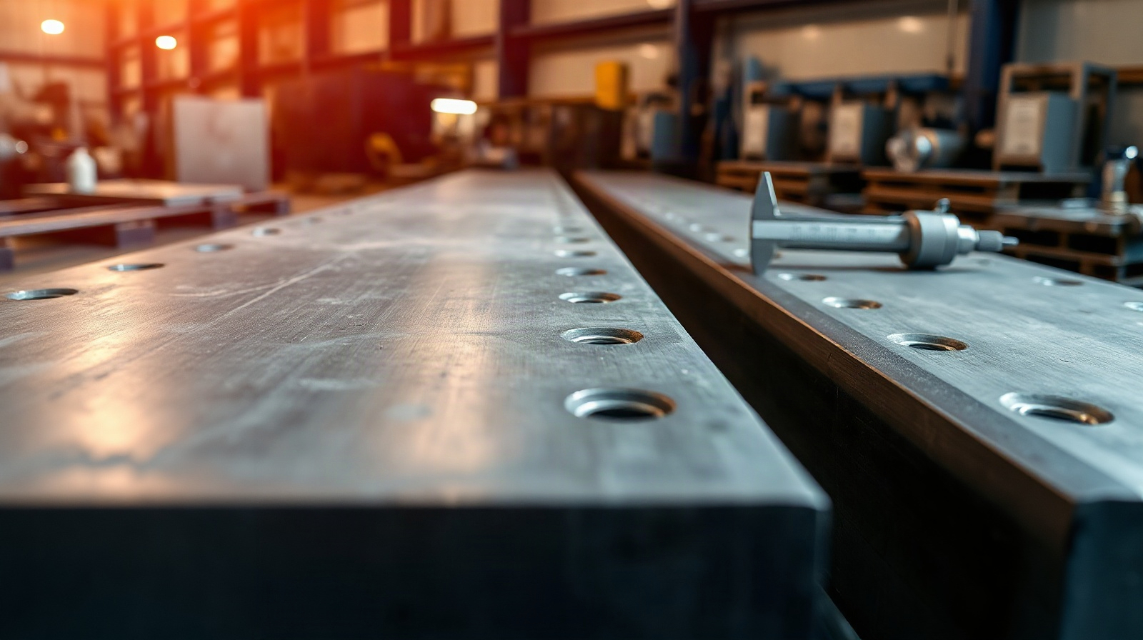
Knowing how to create NC files in Advance Steel is only one part of the fabrication workflow. The more important task is making sure that the exported files represent the approved steel model, the latest connection decisions and the shop drawings sent to production.
Autodesk Advance Steel is designed around structural steel elements such as beams, columns, braces, plates, stairs, railings, bolts, welds and connections. This model-based approach helps detailers keep fabrication information connected instead of recreating it in separate systems. NC files are most useful when that information has been checked before export.
This guide presents a practical workflow for steel fabricators and detailers. It covers Advance Steel NC file export, DSTV-style files, file organisation and checks against drawings. The exact export options and machine requirements can vary by project, fabrication equipment and postprocessor, so always compare the output with your workshop’s accepted format and procedures.
What to Check Before Exporting NC Files
Before generating any steel fabrication NC files, confirm that the model is ready for production. An NC file is not a substitute for design coordination or detailing review. It translates model data into machine-readable information, so an error in the model can be transferred directly to a saw, drill line, coping machine or other fabrication process.
Start with these checks:
- Use the approved model: Confirm that the file contains the latest engineering changes, connection revisions and member sizes.
- Confirm project scope: Identify which members, plates and assemblies are ready for release and which remain under review.
- Check numbering: Ensure that single-part and assembly marks are stable and correspond with the current shop drawings.
- Review drawing status: Do not release NC output for objects that have not passed the project’s internal drawing review.
- Confirm fabrication requirements: Check units, profile naming, hole conventions, cut treatment and the file format accepted by the production equipment.
- Separate revisions: Do not mix superseded NC files with the current release. Use a clear folder and naming structure.
For a BIM exchange with structural engineers, resolve model changes before export. If the engineer changes a column size, base plate, connection or opening after files have been created, regenerate the affected output rather than assuming the previous file remains valid.
Prepare the Steel Model and Fabrication Data
NC output depends on the quality of the Advance Steel model. A line or surface drawn for visual reference may not contain the same fabrication information as a recognised structural steel object. Build production elements using the appropriate Advance Steel objects and connection tools so that profiles, plates, holes, bolts and related information remain available to the export process.
Review the model in a logical sequence:
- Check the structural layout. Compare grids, levels and member positions with the latest engineering information. Look for displaced columns, incorrect beam elevations and braces connected to obsolete locations.
- Check member orientation. A profile can have the correct size but the wrong rotation or justification. This can affect cuts, holes, copes and the way a part is positioned during fabrication.
- Check object identity. Confirm that beams, plates and other parts are modeled as the correct object types, rather than as generic geometry that cannot provide reliable fabrication data.
- Check material and section data. Verify profile names, plate thicknesses, material grades and any project-specific attributes used in drawings or production systems.
- Check numbering after revisions. Re-numbering may be needed after copying, modifying or replacing objects. Make sure the marks shown on drawings match the current model.
Keep the model and drawings in the same release cycle. A common failure is to export a corrected model while distributing drawings created from an earlier state. That creates a traceability problem even if both files look plausible in isolation.
Review Profiles, Plates, Holes and Connections
Detailed inspection of the parts that drive fabrication is essential. The following checks are especially important before Advance Steel NC file export.
Profiles and member ends
Inspect the start and end of each selected profile. Confirm that mitres, cuts, copes, notches and other end treatments are intentional. A member can appear correct in a general arrangement view while a close-up reveals an incorrect cut or a missing cope.
Check the profile orientation and the reference direction used by the model. This matters when a part is rotated, when holes are placed on a particular face or when the fabrication machine interprets the member’s axes.
Plates and fittings
For plates, check thickness, contour, corner treatment, orientation and edge cuts. Verify that part marks and quantities are correct, particularly for repeated stiffeners, gusset plates, splice plates and base plates.
Look for overlapping plates, unintended gaps and plates that are connected visually but have no intended bolts or welds. Also check whether a plate should be included as a separate part or as part of a larger assembly according to the workshop’s process.
Holes, bolts and weld information
Review hole diameter, spacing, edge distances and hole direction. Pay particular attention to holes near profile ends, stiffeners and connection plates. Confirm that bolt groups have the correct quantity and arrangement, and that holes intended for site work are distinguished according to the project’s documentation practice.
Not every production requirement is necessarily represented in the same way in an NC file. Weld symbols, fit-up instructions, site modifications, surface treatment and assembly notes may remain matters for drawings, lists or workshop instructions. Treat the NC file as one deliverable in a coordinated fabrication package.
Connections
Inspect connections from more than one view. Check the relationship between the main member, secondary members, plates, bolts and welds. Pay attention to connection changes made during coordination, because a small change to a connection can alter several parts and their associated files.

Configure the NC File Export
When the model is ready, select the parts or assemblies intended for release and open the NC export workflow available in your Advance Steel installation. The option names and available settings can vary with the software version, regional configuration and production setup, so use the settings agreed with the fabricator and machine supplier.
Before confirming the export, establish the following:
- Output format: Many steel fabrication workflows use DSTV-style NC files, often with an NC1 file extension, but confirm the exact format required by the receiving system.
- Units: Make sure the exported units match the machine, shop standard and project drawings. A unit mismatch can create serious dimensional errors.
- Part selection: Decide whether the export includes single parts, assemblies or a defined release set. Avoid exporting temporary or superseded objects.
- File naming: Use a predictable convention based on part mark, assembly mark, revision or release information where appropriate.
- Profile and plate support: Confirm that the receiving equipment supports the exported section types, cuts, holes and other operations used in the model.
- Postprocessing: If the files pass through a machine-specific postprocessor, verify that the correct configuration is being used for the equipment and material flow.
Do not change export settings simply to make a file open in a viewer. A viewer can confirm that a file is readable, but only a controlled comparison with the model, drawing and machine workflow confirms that it is suitable for production.
Generate and Organize the Files
Export a controlled set rather than creating a large, unexplained folder of files. The release set should be traceable to the model and drawings that were checked.
A practical folder structure may separate:
- the model release;
- NC or DSTV files for single parts;
- assembly information and fabrication drawings;
- material, bolt or part lists;
- review notes and approval records;
- superseded files retained according to the company’s document-control procedure.
After export, check that the expected number of files was created. Compare the file list with the selected objects and the part or assembly list. Missing files can indicate that an object was not selected, was not numbered, was unsupported by the export process or was excluded by a project setting.
Also check for duplicate marks, unexpected overwrites and file names that are difficult for production staff or downstream software to interpret. If a revised part receives the same mark as an earlier release, make the revision status clear in the controlled release process.
Validate NC Output Against Shop Drawings
The central quality-control step is to compare the NC output with the approved shop drawings and the model. Open the files in the relevant viewer or production system and review the geometry, operations and identifiers.
For each selected part or a representative sample from each part type, compare:
- part mark, assembly mark and quantity;
- overall length, width, thickness or profile size;
- member orientation and section rotation;
- cut angles, mitres, copes and notches;
- hole positions, diameters and directions;
- plate contours and corner details;
- connection-related holes and fittings;
- material information and units;
- the drawing views and dimensions used by the workshop.
Use a risk-based review rather than checking only the easiest rectangular plates. Include complex connections, unusual profiles, sloped members, skewed holes, curved or specially cut parts, members with several end treatments and parts changed after engineering coordination.
For a larger release, sample recurring part families as well as unique parts. A repeated connection detail may contain the same mistake across many assemblies, while a unique part may require individual attention. Record discrepancies and regenerate the affected files after correction.
Finally, ask the fabrication team to confirm that the output can be read by its current equipment and production software. A technically valid DSTV file can still require a machine-specific interpretation or an additional workshop step.
Common Problems and Practical Checks
The NC file is missing
Check whether the object was included in the export selection, has a valid part number and is supported by the configured output. Review filters and confirm that the object is not still in an unfinished or excluded status.
The part orientation looks wrong
Compare the model coordinate direction, profile rotation and drawing views. A part may be geometrically correct but presented differently from the workshop’s expected orientation. Confirm the convention with the machine operator before changing the model.
Holes are present but in the wrong position
Inspect the hole group in the model and compare its reference face, spacing and direction with the drawing. Check units and profile orientation. Do not correct the NC file manually without updating the source model and regenerating the controlled output.
The drawing and NC file disagree
Identify which deliverable reflects the latest approved change. Update the model, regenerate drawings and NC files as required, then issue them together. Never rely on a verbal correction for a production-critical dimension.
The machine cannot process the file
Confirm the file format, units, profile support and postprocessor configuration with the equipment supplier or workshop. The solution may involve an approved translation or machine configuration rather than a change to the structural model.
A Repeatable Release Checklist
- Confirm the approved Advance Steel model and current project revision.
- Review profiles, plates, connections, holes, cuts, materials and orientations.
- Update numbering and confirm part and assembly marks.
- Check shop drawings against the model.
- Export the defined release set using the agreed NC or DSTV configuration.
- Verify file count, names, units and required output locations.
- Open and inspect representative files in the production viewer or system.
- Compare NC output with drawings, lists and model geometry.
- Correct discrepancies in the model, then regenerate affected files.
- Release only the coordinated set to fabrication.
This process keeps the 3D model, fabrication drawings and production files connected. It also makes BIM coordination with structural engineers easier because changes can be traced back to the model instead of being corrected independently in several downstream files.
Foire aux questions
What file format does Advance Steel use for steel fabrication?
Many steel workflows use DSTV-style NC files, commonly associated with NC1 output. The exact format and postprocessing requirements depend on the receiving fabrication equipment, so confirm the accepted configuration before release.
Can I create NC files before shop drawings are approved?
You can generate preliminary output for checking, but production files should normally be released only after the model and relevant shop drawings have passed the project’s review process.
Why should I compare NC files with shop drawings?
The comparison can reveal differences in orientation, cuts, holes, part marks, units or connection details. It confirms that the machine-readable output represents the information communicated to the workshop.
Should I edit an NC file manually when I find an error?
As a controlled practice, correct the Advance Steel model or approved export configuration and regenerate the file. Manual edits can break traceability and leave the drawing, model and production output inconsistent.
Which Advance Steel licence is suitable for this workflow?
Autodesk Advance Steel is intended for structural steel detailing and fabrication workflows on Windows. Licences are available for one or three years, with the licence assigned to an Autodesk account. Check the current product page for the available option and current price.
Genuine Autodesk Advance Steel licences are available from KEYFORREST with instant electronic delivery. Use the current product information and your workshop’s machine requirements to select the appropriate licence and export workflow.

À propos de Marios Chaidousis
Articles associés
Comment sécuriser les fichiers de projets BIM en ingénierie des structures
-
Publié par Marios Chaidousis
Les modèles contradictoires, les plans obsolètes et les rapports de calcul non suivis peuvent créer de sérieux risques de coordination. Ce guide explique comment les bureaux d’ingénierie des structures peuvent sécuriser leurs fichiers de projets BIM grâce à un accès contrôlé, à une gestion des versions et à des procédures claires de validation.
Advance Steel or AutoCAD for Steel Shop Drawings?
-
Publié par Marios Chaidousis
The right choice depends on whether your team mainly produces carefully controlled drawings or needs a connected steel model that drives detailing and fabrication information. This comparison focuses on real shop-floor and detailing tasks.
Advance Steel vs Revit for Steel Detailing
-
Publié par Marios Chaidousis
Advance Steel and Revit can both represent structural steel, but they support different stages of a project. This comparison explains where each tool fits and when a combined workflow is the better choice.

Autodesk Advance Steel for Steel Fabricators
-
Publié par Marios Chaidousis
Autodesk Advance Steel connects structural steel modeling, connection design, shop drawings, material data and production outputs in one workflow. This guide explains how fabrication and detailing teams can use it from engineer coordination to workshop preparation.

Steel Detailing Workflow: Model to NC File
-
Publié par Marios Chaidousis
A reliable steel detailing workflow connects engineering information to fabrication documents and machine-ready output. This guide follows the handoff from analysis and BIM coordination through connections, shop drawings and NC files.
Revit MEP Clash Detection for HVAC, Plumbing and Electrical
-
Publié par Marios Chaidousis
A practical Revit MEP clash detection checklist for finding and resolving conflicts between HVAC ductwork, plumbing, electrical systems and building elements. Learn how to prepare linked models, review interference results and record decisions for construction.

Flux de travail Revit IFC pour les architectes : guide de coordination
-
Publié par Marios Chaidousis
Un flux de travail Revit IFC fiable aide les architectes à échanger des données BIM ouvertes utiles avec les ingénieurs tout en conservant la maquette Revit native comme source du projet. Ce guide couvre la préparation, l’exportation, la vérification, la coordination et le contrôle des versions.

From Structural Analysis to Reinforcement Drawings
-
Publié par Marios Chaidousis
A reliable reinforced concrete BIM workflow does more than transfer forces between software. It connects design assumptions, analysis results, engineering decisions, reinforcement models and issue-ready drawings while keeping responsibility with the engineer.

Créer des PDF prêts pour les permis à partir de Revit et AutoCAD
-
Publié par Marios Chaidousis
Un flux de travail PDF fiable pour les dessins d’architecture ne se limite pas à exporter un fichier. Préparez correctement les vues, les feuilles et les mises en page, puis vérifiez l’échelle, les épaisseurs de ligne, l’ordre des pages et l’intégralité du document avant d’émettre les documents PDF destinés aux permis de construire ou aux appels d’offres.

Robot Structural Analysis Eurocode Workflow with Revit
-
Publié par Marios Chaidousis
A practical guide for structural offices using Robot Structural Analysis and Revit for Eurocode-based design. Keep assumptions, verification decisions, analytical models and BIM deliverables connected without hiding engineering judgement.

Best BIM Software for Structural Engineering Offices
-
Publié par Marios Chaidousis
The best BIM software for structural engineers is usually a coordinated workflow rather than one application. This guide maps Revit, Robot Structural Analysis and Advance Steel to the daily work of a structural design office.

How to Coordinate Robot Analysis with Revit Models
-
Publié par Marios Chaidousis
A reliable Robot Revit integration workflow is more than pressing an exchange button. Learn how to prepare, compare and update structural models while controlling geometry, supports, releases, loads and design information.