
Blog
PowerShape for Mould Design: Prepare Better Tooling Geometry

Mould and die shops rarely receive perfect geometry. A customer may provide a neutral CAD file with gaps, overlapping faces or unclear design intent. A legacy tool may exist only as an old model, scan or drawing. Even a well-designed part can require careful preparation before electrodes, inserts, cores, cavities and machining strategies can be planned.
PowerShape for mould design is relevant to this stage of the workflow: bringing complex digital design work into a controlled Autodesk-based process and preparing geometry for downstream manufacturing tasks. It is especially worth evaluating when your work involves complex surfaces, imported models, toolmaking and geometry that needs more attention than a standard mechanical part.
This article focuses on the practical problems faced by mould making, die design and CNC machining shops. It also explains what to check before choosing PowerShape mould design software and how it compares with general-purpose mechanical CAD.
What mould and die designers need from CAD software
Standard part design often begins with a known material, a planned feature tree and a relatively clear design intent. Mould and die design is different. The model may be incomplete, created in another system or based on a physical component. The important question is not only whether the shape can be displayed, but whether it is reliable enough for design decisions and CAM programming.
A useful CAD for toolmaking workflow should help the team work methodically with:
- Complex surface geometry: automotive, consumer-product and industrial parts can contain flowing transitions, variable curvature and difficult blends.
- Imported models: neutral files may contain small gaps, duplicate faces, broken edges or tolerances that do not match the shop’s manufacturing process.
- Tooling features: the finished part is only the starting point. The shop must reason about separation, inserts, clearances, shut-offs, machining access and assembly.
- Legacy data: previous moulds and dies may need modification without a clean parametric history.
- Manufacturing hand-off: the geometry must be understandable to the person programming milling operations, including complex 3-axis and 5-axis work.
- Inspection and communication: designers, programmers and machinists need a shared model and a clear way to identify uncertain areas.
PowerShape should therefore be assessed as part of the complete process, not as an isolated modelling purchase. Ask whether it fits the way your shop receives data, repairs geometry, develops tooling and passes models to CAM.
Building and editing complex surfaces
Complex surfaces are often the reason a mould or die project cannot be treated like an ordinary prismatic component. A visible defect may be small, but it can affect the quality of the mould, the continuity of a machined area or the way a toolpath behaves near a transition.
When evaluating PowerShape complex surfaces workflows, concentrate on practical questions rather than the number of modelling commands in a product brochure:
- Can the team identify which faces are design-critical and which can be rebuilt or simplified?
- Can surface boundaries and transitions be reviewed clearly enough to locate discontinuities?
- Can the designer preserve the intended form while making a controlled repair?
- Can the resulting model be transferred to the CAM process without creating avoidable ambiguity?
A typical workflow starts by isolating the product geometry from the tooling geometry. The designer reviews the supplied model, identifies the parting region and marks areas that need a new surface or a controlled extension. The next step is to establish the design logic for the tool: where the cavity and core will separate, which surfaces require shut-offs and where inserts or replaceable elements may be sensible.
For a consumer-product mould, for example, a small mismatch around a curved housing may not be visible in a shaded view. It can become important when creating a parting surface or programming a finishing pass. The designer should check the continuity of the surrounding faces, document the repair and confirm that the repaired area still reflects the intended part shape.
PowerShape is best considered here as a geometry-preparation environment within an Autodesk-based workflow. Do not assume that a CAD licence alone replaces dedicated CAM programming, toolpath verification, post-processing or machine control. Those responsibilities may require separate software and established shop procedures.
Preparing imported and legacy geometry
Imported geometry is one of the main reasons toolmaking companies look beyond a basic mechanical CAD workflow. A STEP, IGES or other exchange file may open successfully and still be unsuitable for immediate tooling work. The model can contain tiny openings, trimmed surfaces that do not meet correctly, sliver faces or inconsistent tolerances.
A disciplined preparation process helps prevent these issues from reaching the CAM programmer:
- Keep the original file unchanged. Save an identifiable working copy and record the source, revision and date.
- Inspect the model before editing. Look for open boundaries, overlapping geometry, unexpected gaps, missing faces and areas that do not match the supplied drawing or reference.
- Separate certainty from assumption. Mark what comes directly from the customer and what has been reconstructed or inferred by the shop.
- Repair only what is necessary. Uncontrolled remodelling can alter the part and make later comparison difficult.
- Check transitions after repair. A closed model is not automatically a good tooling model; surface quality and design intent still matter.
- Export a controlled manufacturing version. Use clear revision names and communicate any repaired or replaced regions to CAM and inspection staff.
This approach is also useful for legacy moulds. A previous project may contain valuable geometry but little useful feature history. Instead of rebuilding everything, the designer can identify the surfaces that must remain unchanged, repair the regions that block the new task and create only the additional tooling geometry required for the current revision.
Reverse engineering requires extra care. A scan or measured reference describes an existing object, but it does not automatically explain the desired nominal design, shrinkage allowance, parting strategy or manufacturing tolerance. PowerShape can be considered when your team needs a structured way to work with difficult digital geometry, but the final design decisions still require manufacturing knowledge and, where relevant, customer approval.
Design checks before CAM programming
Geometry preparation is valuable because CAM programming becomes more predictable when the model has been reviewed before it reaches the programmer. The precise checks depend on the project, machine and CAM system, but a mould or die review commonly covers the following areas:
- Parting logic: confirm that the intended separation is understood and that critical surfaces are assigned to the correct tooling side.
- Shut-offs and openings: identify holes, openings and edge conditions that could require additional tooling surfaces or inserts.
- Access: review whether the required regions can be reached with the planned tool orientations, holders and extensions.
- Small radii and narrow areas: flag regions that may demand small cutters, multiple operations or a design decision before programming.
- Surface continuity: check transitions that will affect finishing quality, toolpath direction or visible part surfaces.
- Stock and clearances: confirm that the model can be related to the intended blank, electrode or assembly without collisions in the next stage.
- Revision status: ensure that the programmer is using the approved geometry and knows which areas were repaired or reconstructed.
These checks do not prove that a toolpath is safe. Toolpath simulation, machine-specific collision checking, post-processor validation and shop-floor verification remain important. A good geometry model reduces avoidable problems; it does not remove the need for CAM and machining controls.

PowerShape compared with general-purpose mechanical CAD
General-purpose mechanical CAD remains the right choice for many products. It is usually strong when a design team creates dimension-driven parts, assemblies, drawings and controlled parametric revisions. Mould and die projects, however, often spend more time cleaning, interpreting and adapting geometry than creating a part from a blank feature history.
| Requirement | General-purpose mechanical CAD | PowerShape for mould design | Practical recommendation |
|---|---|---|---|
| Dimension-driven product design | Often the natural starting point for features, assemblies and design revisions. | Evaluate it as a complementary tool rather than an automatic replacement. | Use the mechanical CAD system when the product design history is the main requirement. |
| Imported and damaged geometry | May be adequate for simple repairs, but the workflow depends heavily on the system and model condition. | Consider PowerShape when complex geometry preparation and repair are recurring shop tasks. | Test representative customer files before making a purchase decision. |
| Complex mould and die surfaces | Can handle many surfaces, but the best workflow may require specialist knowledge and additional tools. | Relevant for teams whose daily work centres on difficult tooling geometry. | Choose the environment that gives designers the most controlled surface workflow for their actual projects. |
| CAM programming | Mechanical CAD does not necessarily provide the required machining workflow. | PowerShape should not be assumed to replace dedicated CAM. | Confirm how models move into the shop’s CAM, verification and post-processing process. |
| Legacy and reverse-engineering work | Can be effective when the original design intent and references are available. | Worth evaluating where the team must interpret and prepare non-ideal geometry. | Use sample legacy and measured data, not only a clean demonstration model. |
| Procurement and deployment | Depends on the selected CAD product and licence terms. | Autodesk PowerShape licences are assigned to an Autodesk account. | Plan account ownership, user access and one-device use before deployment. |
The clearest recommendation is usually a combined workflow. Keep the system that owns the product design where it is strongest, and evaluate PowerShape for the geometry-heavy work that makes mould and die projects different: complex surfaces, imported data, tooling preparation and the transition into manufacturing.
Which PowerShape licence fits a toolmaking shop?
Autodesk PowerShape is available for one or three years, for one device. The licence is assigned to an Autodesk account. If the user does not already have an account, one can be created using the purchaser’s name and email address before login.
For an individual designer or a small shop, a one-year term can be suitable when the team wants to validate the workflow against real mould and die projects. A three-year term may fit a shop that has already confirmed the software’s role in its geometry-preparation process and wants a longer planning horizon. In both cases, check which person will control the Autodesk account and which workstation will use the licence.
The listed interface languages include English, German, French, Italian, Spanish, Russian, Brazilian Portuguese, Japanese and Simplified Chinese. Confirm the required language and the current technical requirements before deployment on a Windows workstation.
How to evaluate PowerShape with your own projects
A product demonstration can hide the problems that matter most to a toolmaking shop. Use a short, representative evaluation based on real files:
- Select one clean model, one imported model with known defects and one legacy or measured example.
- Record the time needed to inspect and prepare each model.
- Ask a designer to document repairs and a CAM programmer to review the manufacturing hand-off.
- Check whether the revised geometry is easy to identify, archive and compare with the original.
- Test the most difficult surfaces, not only the simplest part of the project.
- Confirm the Autodesk account, Windows workstation and one-device licensing arrangements.
Also define acceptance criteria. For example, the team might require a closed and traceable model, clearly identified repaired regions, an agreed file format for CAM and a review record for critical tooling surfaces. This turns a software trial into a useful process test.
Domande frequenti
Is PowerShape suitable for mould design?
PowerShape is worth evaluating for mould design when the work centres on complex surfaces, imported or legacy geometry and preparation before manufacturing. Test it with representative files because suitability depends on your workflow and CAM system.
Does PowerShape replace CAM programming software?
Do not assume that it does. PowerShape can be evaluated for geometry preparation, while dedicated CAM, simulation, post-processing and machine verification may still be required.
Can PowerShape help with reverse engineering?
It can be considered for workflows involving difficult or measured geometry, but a scan does not define design intent by itself. Nominal shape, allowances, tolerances and tooling decisions still require engineering review.
Is PowerShape useful for 5-axis machining projects?
It can be relevant where complex geometry must be prepared for downstream 5-axis work. Confirm the complete connection with your CAM software and verify access, holders, collisions and post-processing separately.
Where can I obtain a genuine PowerShape licence?
Genuine Autodesk PowerShape licences are available from KEYFORREST with instant electronic delivery. Review the current product page for the available term and licence details before ordering.

Informazioni su Marios Chaidousis
Articoli correlati

Windows 11 for CNC Workstations: Migration Checklist
-
Pubblicato da Marios Chaidousis
A Windows 11 migration can affect CAM software, post-processors, drivers, machine settings and production schedules. Use this practical checklist to test compatibility, protect manufacturing data and move CNC workstations in controlled stages.

From Scan to Toolpath: A CNC Reverse-Engineering Workflow
-
Pubblicato da Marios Chaidousis
A reliable reverse engineering CNC workflow does more than convert a scan into a surface model. It connects measurement, geometry repair, machining strategy, verification and revision control so that an inherited or physical part can become repeatable CNC output.
Inventor vs PowerShape for Mould Design
-
Pubblicato da Marios Chaidousis
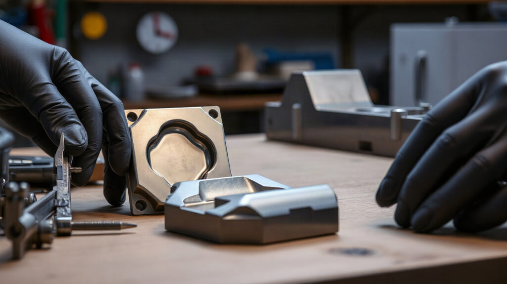
Inventor and PowerShape suit different mould and die workflows. This comparison focuses on parametric mechanical design, complex geometry, manufacturing handover and the situations where a shop may use both.

PowerShape vs PowerMill: Which Comes First?
-
Pubblicato da Marios Chaidousis
PowerShape and PowerMill are not interchangeable alternatives. PowerShape belongs at the design and geometry-preparation stage, while PowerMill is used to program CNC machining operations.

Best CAM Software for CNC Job Shops: A Practical Guide
-
Pubblicato da Marios Chaidousis
The best CAM software for CNC machining depends on the parts you make, the machines you run and the experience of your programmers. This practical guide compares PowerMill and Autodesk’s Product Design & Manufacturing Collection by real job-shop workflows.
PowerMill for 5-Axis CNC Machining
-
Pubblicato da Marios Chaidousis
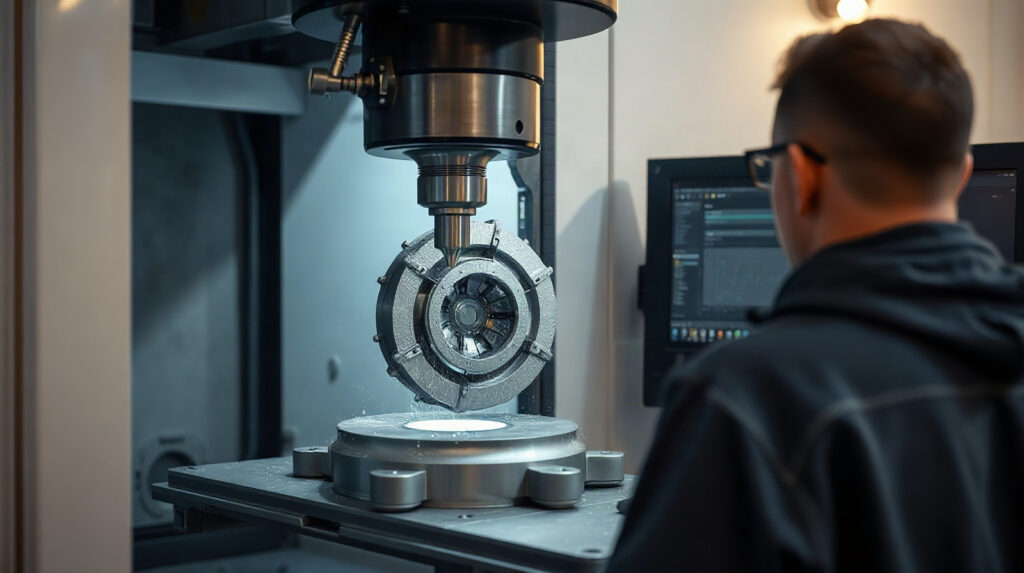
PowerMill is CAM software for manufacturers programming demanding 3-axis and multi-axis CNC work. This guide explains where it fits in 5-axis machining, toolmaking, mould making and complex-surface production.