
Blog
From Scan to Toolpath: A CNC Reverse-Engineering Workflow

Reverse engineering often starts with incomplete information: a worn mould insert, a physical component without CAD data, an inherited model in an obsolete format, or a part that must be reproduced with controlled changes. The objective is not simply to copy visible geometry. A useful result must be clean enough to design with, precise enough to inspect, and structured enough to manufacture repeatedly.
This reverse engineering CNC workflow follows a practical sequence: capture reference geometry, organise and assess the data, repair or rebuild the model, define manufacturing regions, create and verify toolpaths, then document the result for future production. The exact commands depend on the scanner, inspection system, postprocessor and CNC machine, but the logic applies across toolmaking, mould making and complex component machining.
1. Define the reverse-engineering objective
Before scanning or modelling, decide what the final output must achieve. Different objectives require different levels of measurement and modelling:
- Reproduction: recreate the external form of an existing part as closely as practical.
- Repair or replacement: recover the geometry of a worn or damaged component, while separating original design intent from wear.
- Design modification: use the existing form as a starting point for new clearances, parting conditions, inserts or functional changes.
- Manufacturing recovery: rebuild enough reliable geometry to produce a replacement when the original CAD or CAM data is unavailable.
- Inspection-led reconstruction: compare measured data with nominal geometry and decide which areas need remodelling.
Also record the manufacturing constraints at this stage. Note the stock condition, datum scheme, available cutters, machine axes, workholding, required surface finish and any regions that must remain untouched. A scan can reproduce a physical state, but it cannot tell you whether a surface is worn, distorted by clamping, deliberately relieved or intended to be nominal.
2. Capture and organise reference geometry
Collect all available evidence rather than relying on one scan. Depending on the job, this may include a point cloud, polygon mesh, probing results, photographs, existing drawings, measuring reports, tooling dimensions and a previous CAM setup. Keep the original data unchanged and create working copies for processing.
Use a consistent coordinate system. Establish a practical manufacturing datum based on the part’s functional faces, locating features or planned workholding. If the component will be machined in several setups, define how the datum transfers between them. A coordinate system that works for inspection may not be convenient for programming, so record both the measurement orientation and the manufacturing orientation when necessary.
Inspect the captured data before attempting to fit surfaces. Look for holes in the scan, overlapping scans, noise around sharp edges, reflections, missing undercuts and areas hidden by fixtures. A dense mesh is not automatically an accurate mesh. Sampling quality, scanner calibration, surface reflectivity and alignment all affect the result.
Keep useful metadata with the project:
- source device and measurement date;
- scan or probing settings where available;
- alignment method and reference features;
- known dimensions used for scale checks;
- areas excluded because they were inaccessible;
- assumptions about worn, damaged or contaminated surfaces.
This information prevents a later programmer from treating uncertain areas as confirmed design intent.
3. Clean and repair the model
The next stage is to distinguish measurement noise from meaningful form. Remove isolated points and obvious artefacts, but avoid smoothing away small radii, parting details or tool-relevant transitions. Keep a separate copy of the raw scan so that every clean-up decision can be revisited.
For mesh-based data, check for holes, non-manifold regions, flipped normals, duplicate faces and self-intersections. Close only the gaps that can be justified from surrounding geometry or other evidence. A large missing area should normally be reconstructed as a designed surface, not hidden with an automatic fill that has no clear engineering basis.
Alignment is equally important. Use stable datums and repeatable features rather than a visual best fit alone. A global best-fit alignment can distribute error across the entire part and conceal a meaningful mismatch at a critical face. For reverse engineering moulds, align the data to functional parting, insert or locating references where these are known.
At this point, create inspection checks. Compare selected sections, heights, hole centres, wall thicknesses and key distances against available measurements. Mark uncertain regions in the working model or project notes. The result should be a controlled reference model, not merely a visually attractive mesh.
4. Rebuild surfaces and recover design intent
There are several valid outcomes between using a raw mesh and rebuilding a complete parametric CAD model. Choose the simplest representation that is accurate enough for the job.
- Reference mesh: useful for visual comparison, rough stock preparation and limited machining where the mesh quality is sufficient.
- Repaired solid or surface model: appropriate when boundaries, holes and major faces can be recovered with confidence.
- Hybrid model: combines measured freeform surfaces with reconstructed planes, cylinders, fillets, holes and other regular features.
- Designed replacement model: required when wear, damage or manufacturing allowances mean that the physical part should not be copied literally.
Autodesk PowerShape can be used as the design-focused environment for bringing complex digital geometry into a controlled workflow. In a PowerShape reverse engineering process, use the measured data as evidence, then rebuild important boundaries and surfaces with deliberate continuity and clear references. Exact operations and available options depend on the installed version and data type, so confirm the current Autodesk documentation for the specific workflow.
Surface quality matters more than model complexity. Check tangency between adjoining faces, continuity across repaired regions, sharp edges that must remain sharp, and transitions that need a defined radius. For mould and die work, also identify parting surfaces, shut-offs, inserts, sliders, deep cavities and steep walls. These regions often determine whether a model can be machined efficiently.
Do not automatically convert every scanned feature into a nominal CAD feature. A worn corner may need a designed radius; a damaged cavity may need to be rebuilt from symmetry or adjacent geometry; and an irregular face may require engineering review. Document these decisions so that the finished model is understandable to the next programmer or toolmaker.
5. Prepare the model for machining
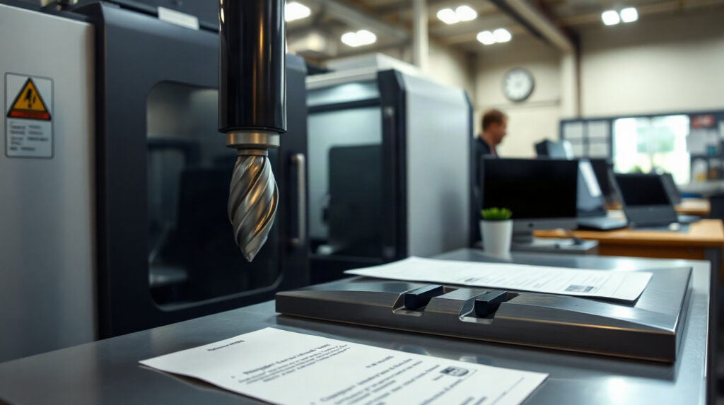
Before creating toolpaths, make the manufacturing model explicit. Confirm the stock, finished boundaries, machining datums, safe areas and regions that will be produced by other processes. Separate the model into logical machining regions when this improves control: planar faces, shallow slopes, steep walls, deep pockets, fillets, electrodes, inserts or freeform surfaces.
Define allowances deliberately. A model used for roughing may include stock, while a finishing reference should normally represent the intended finished surface. Mould components may need different allowances for roughing, semi-finishing and finishing, especially where a later fitting or polishing operation is planned.
Check accessibility before programming. For every surface, ask:
- Can the selected machine reach it in the planned setup?
- Is a tool holder, spindle nose or fixture likely to collide?
- Is the cutter diameter suitable for the smallest concave radius?
- Will a shorter tool improve rigidity and surface finish?
- Is a 3-axis solution sufficient, or is indexed or simultaneous multi-axis motion needed?
This is where design and CAM decisions meet. A surface may be geometrically valid but impractical to cut in the available machine configuration. Adjust the model, setup or machining plan before investing time in detailed toolpath programming.
6. Create the scan to CNC toolpath
Autodesk PowerMill is intended for demanding CNC programming where controlled tool movement, surface finish and machining efficiency matter. In a PowerMill reverse engineering workflow, import or reference the prepared geometry, define the machine and workholding context, then build operations in a sequence that reflects how the part will actually be produced.
- Set up the stock and datums. Define the initial stock, work coordinate system, fixture situation and any known machine limits.
- Rough the major volume. Remove material efficiently while protecting fixtures and leaving an intentional allowance for later operations.
- Rest-machine remaining material. Use smaller tools or targeted strategies in corners, fillets, pockets and regions left by the roughing cutter.
- Semi-finish complex surfaces. Establish a more consistent allowance and expose areas that require close inspection.
- Finish by region. Select strategies suitable for shallow surfaces, steep walls, flat areas, pencil regions and tight concave details.
- Use indexed or multi-axis motion where justified. Reorient the tool to improve access, reduce tool length or control contact conditions, while respecting the machine and postprocessor.
- Link operations safely. Review retracts, leads, links, entry moves and transitions rather than accepting them without inspection.
A scan to CNC toolpath should not follow every small variation in noisy data. Excessive detail can produce unstable motion, unnecessary code and poor surface finish. Filter or rebuild the geometry where appropriate, then use machining tolerances that reflect the required accuracy, cutter size, machine capability and inspection method.
For 5-axis milling, tool-axis control is part of the engineering decision, not just a visual setting. Check tilt, lead and collision avoidance against the actual holder, spindle and fixture. A theoretically accessible surface may still be impossible with the selected tool assembly.
7. Verify the toolpath before cutting
Verification should happen at several levels. First, review the toolpath visually for missed regions, excessive linking, abrupt direction changes, gouges and areas where the tool cannot reach the intended surface. Next, simulate material removal using the actual stock and fixture assumptions. Compare the simulated result with the target model and inspect leftover material, overcut areas and collision risks.
Machine simulation is especially important for multi-axis work. Confirm rotary-axis direction, machine limits, singularity behaviour, rotary rewinds and the relationship between the programmed coordinate system and the machine’s real setup. A correct-looking toolpath in a generic view can still produce an invalid movement after posting.
Review the postprocessed NC output according to your shop’s normal procedure. Check the correct tool numbers, offsets, work coordinates, spindle and feed commands, coolant instructions and safe start position. The CAM simulation is not a substitute for confirming that the postprocessor matches the intended CNC machine and controller.
Finally, define an inspection plan for the first piece. Measure critical datums, freeform surfaces, wall thicknesses, holes and areas where the scan or reconstruction was uncertain. Feed the findings back into the model and process rather than making undocumented edits at the machine.
8. Document revisions for repeat production
Reverse engineering becomes valuable when the result can be reproduced and maintained. Store the raw measurement data, cleaned reference data, rebuilt CAD model, CAM project, tool list, postprocessed NC file and inspection report under a controlled naming scheme. Record the revision, date, responsible person and reason for each significant change.
Separate source evidence from approved manufacturing geometry. A future user should be able to tell which surfaces came directly from measurement, which were reconstructed, and which were intentionally redesigned. Keep notes about uncertain areas, manual adjustments, approved allowances and machine-specific assumptions.
For repeat work, create a short setup record covering datums, workholding, tool assemblies, probing or inspection points and any known finishing operations. This reduces dependence on the original programmer and makes later replacement work more predictable.
PowerShape or PowerMill: which tool fits the workflow?
| Need | More relevant tool | Recommendation |
|---|---|---|
| Clean, assess and rebuild complex measured geometry | Autodesk PowerShape | Choose PowerShape when the main challenge is turning inherited or measured geometry into a controlled design model. |
| Program roughing, finishing and multi-axis machining | Autodesk PowerMill | Choose PowerMill when the model is ready and the main requirement is controlled CNC toolpath creation and verification. |
| Complete reverse engineering of moulds or dies | PowerShape plus PowerMill | Use the tools together when geometry reconstruction and complex machining are both central to the job. |
| Simple prismatic replacement parts | Existing CAD and CAM tools may be sufficient | Do not introduce a specialist reverse-engineering workflow if conventional measurements and modelling already provide reliable data. |
PowerShape does not replace measurement hardware, engineering judgement or inspection. PowerMill does not repair poor source geometry or decide whether a worn surface represents the intended design. Together, they can support a structured process, but the quality of the result still depends on measurement, datums, model interpretation, machine data and verification.
Perguntas frequentes
What is a reverse engineering CNC workflow?
It is a controlled sequence that converts measured or inherited geometry into a manufacturable model, verified CNC toolpaths and documented production information. It includes interpretation and validation, not only scanning.
Can a raw scan be used directly for CNC machining?
Sometimes, but it is rarely the safest default. Noise, holes, alignment errors and worn features can create unstable or misleading toolpaths. Clean, inspect and rebuild critical regions before machining.
Is PowerShape used for reverse engineering moulds?
PowerShape can support the design and geometry-reconstruction stage for complex measured or inherited forms. Confirm the exact tools and data formats available in your installed version before planning a production workflow.
When is PowerMill needed for a scan to CNC toolpath?
PowerMill is relevant when the prepared geometry must be converted into controlled roughing, rest-machining, finishing or multi-axis toolpaths for demanding CNC work.
How should revisions be managed?
Keep the raw scan unchanged, identify the approved model revision, store the CAM project and NC output together, and record geometry changes, allowances, machine assumptions and inspection results.
Genuine Autodesk PowerShape and PowerMill licences are available from KEYFORREST with instant electronic delivery. Check the current product page for the available licence term, language and platform details before purchasing.

Sobre Marios Chaidousis
Artigos relacionados
Windows 11 for CNC Workstations: Migration Checklist
-
Publicado por Marios Chaidousis
A Windows 11 migration can affect CAM software, post-processors, drivers, machine settings and production schedules. Use this practical checklist to test compatibility, protect manufacturing data and move CNC workstations in controlled stages.
Inventor vs PowerShape for Mould Design
-
Publicado por Marios Chaidousis
Inventor and PowerShape suit different mould and die workflows. This comparison focuses on parametric mechanical design, complex geometry, manufacturing handover and the situations where a shop may use both.

PowerShape for Mould Design: Prepare Better Tooling Geometry
-
Publicado por Marios Chaidousis
Mould and die work often starts with incomplete, imported or difficult geometry rather than a clean part model. This guide explains where PowerShape for mould design fits into geometry preparation, surface work and CAM-ready inspection.

PowerShape vs PowerMill: Which Comes First?
-
Publicado por Marios Chaidousis
PowerShape and PowerMill are not interchangeable alternatives. PowerShape belongs at the design and geometry-preparation stage, while PowerMill is used to program CNC machining operations.

Best CAM Software for CNC Job Shops: A Practical Guide
-
Publicado por Marios Chaidousis
The best CAM software for CNC machining depends on the parts you make, the machines you run and the experience of your programmers. This practical guide compares PowerMill and Autodesk’s Product Design & Manufacturing Collection by real job-shop workflows.
PowerMill for 5-Axis CNC Machining
-
Publicado por Marios Chaidousis
PowerMill is CAM software for manufacturers programming demanding 3-axis and multi-axis CNC work. This guide explains where it fits in 5-axis machining, toolmaking, mould making and complex-surface production.