
Blogg
Create Production Drawings in Autodesk Inventor
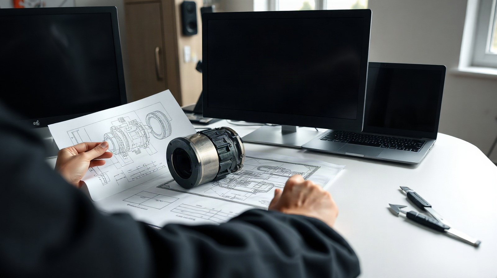
Production drawings connect a 3D design to the people who manufacture, inspect, assemble and service the finished product. A model may communicate design intent to an engineer, but the factory usually needs controlled documentation: dimensions, tolerances, material information, section views, hole details, assembly references and revision status.
Autodesk Inventor Professional provides a dedicated environment for parametric 3D parts, detailed assemblies and technical documentation. Its parametric approach links dimensions, constraints and features, so changes such as a revised hole diameter, wall thickness or component length can update through the design. The important point is to treat the drawing as part of the design workflow, not as a separate illustration created at the end.
This guide describes a practical process for mechanical engineers and product designers working with individual components, assemblies and production teams. The exact commands and available options can vary by Inventor version, template and company configuration, so use your organisation’s approved standards for final release.
Prepare the 3D part or assembly
A reliable drawing begins with a reliable model. Before creating a sheet, review the 3D part or assembly as if you were preparing it for another engineer to manufacture and inspect.
- Confirm the design intent. Check that sketches, constraints and features describe the intended function. Avoid using accidental geometry or unconstrained dimensions as the basis for a production-critical feature.
- Check important dimensions. Review hole diameters, spacing, wall thicknesses, lengths, angles, interfaces and clearance areas. A drawing can only document the model that exists; it cannot correct an incorrect feature.
- Use meaningful component and feature names. Clear names make it easier to find the correct part in an assembly and reduce mistakes when several similar components are present.
- Review assembly relationships. Confirm that the correct components are included and that their positions represent the intended assembled condition. Look for missing fasteners, duplicate parts, unexpected interference or a component shown in the wrong orientation.
- Decide what needs its own drawing. Machined parts, fabricated items and purchased components often require different documentation. An assembly drawing should not be overloaded with every dimension needed to manufacture each individual part.
For designs that have gone through calculations or simulation, use approved results to support engineering decisions, but do not treat a simulation result as a manufacturing instruction by itself. The production drawing still needs the dimensions, tolerances and notes required for making and checking the physical item.
Set up drawing views and sheet formats
Create a drawing from the correct model and select a sheet format that suits the manufacturing task. A small turned component may need one clearly dimensioned sheet, while a large machine assembly may require several sheets, detail views and a parts list.
Begin with a primary view that communicates the function and shape of the part. Add projected views only when they provide useful information. More views do not automatically make a drawing clearer. Each view should help the reader understand a feature, define a dimension or verify an interface.
For a part, a practical view arrangement may include:
- A main orthographic view showing the most important functional features.
- Projected views for depth, height or hidden relationships that cannot be read from the main view.
- A section view for internal bores, wall thicknesses, cavities or intersecting features.
- A detail view for small holes, edge treatments, grooves or complex geometry.
- An isometric view when it helps the reader recognise the part, provided it does not replace required orthographic information.
For an assembly, choose views that explain how components relate to one another. An exploded view may help with assembly instructions, while a normal assembled view is usually better for showing interfaces, mounting positions and overall arrangement. Use section or detail views where internal components or connection points would otherwise remain unclear.
Set the scale so that dimensions and notes remain readable when the drawing is printed or exported. Leave sufficient space around views for annotations. Crowding a sheet at the beginning usually creates more rework later, especially when a model change requires a view, note or parts list to expand.
Use your company’s approved title block, border, projection method, unit system, material fields and revision fields. Do not copy information manually between unrelated files when a controlled template or drawing property can provide it. Consistent sheet formats make drawings easier for production, purchasing, inspection and external suppliers to read.

Add dimensions, tolerances and annotations
Dimensions should describe how the component is made and how its critical features are verified. Start with the functional requirements, then add the dimensions needed to locate and manufacture those features. Avoid dimensioning every visible edge without considering the manufacturing process.
For a machined part, consider which dimensions define the datum structure, hole locations, fits, thicknesses and interfaces. For a fabricated part, consider bend locations, cut profiles, weld-related information and the conditions needed for inspection. The appropriate information depends on the process and your company’s drawing standard.
Use a consistent annotation strategy:
- Locate features from sensible references. Dimensioning a hole pattern from a functional datum is often clearer than chaining unrelated dimensions.
- Separate general information from feature-specific information. Put broad requirements in a general notes area and keep local requirements close to the relevant feature.
- Use tolerances deliberately. A tight tolerance can affect cost, inspection and manufacturing method. Apply it because the function requires it, not simply because the nominal value looks precise.
- Identify materials and finishes. Include the information needed by production and purchasing, using the terminology approved by your organisation.
- Make symbols and notes readable. Check text height, line weight, arrow placement and spacing at the intended output size.
Do not rely on the model alone to communicate a requirement. A feature may be visible in 3D but still need an explicit dimension, tolerance or note on the drawing. Conversely, do not add an annotation that conflicts with the geometry or with another requirement elsewhere on the sheet.
Document assemblies and parts clearly
Inventor parts and assembly drawings serve different purposes. A part drawing normally defines one component for manufacture and inspection. An assembly drawing explains how components fit together and may provide identification, orientation and installation information.
For an assembly drawing, make the component structure easy to follow. Use item numbers consistently and make sure they correspond to the parts list. The list should identify the components required for the assembly without ambiguity. If several components look similar, include a useful part or drawing identifier rather than relying on appearance alone.
Show the interfaces that matter: mounting holes, shafts, bearing seats, connection points, clearances and orientation features. A general assembly view may not provide enough information for an important interface, so add a section or detail view where necessary. Use exploded views only when they improve understanding of assembly sequence or component identification.
For individual part drawings, avoid placing manufacturing dimensions on an assembly sheet when the part requires its own controlled definition. The assembly drawing can identify the component and explain its position; the part drawing should contain the information needed to produce and inspect it.
When a design includes a factory layout or a larger equipment arrangement, keep the scope clear. An Inventor assembly drawing can document the relationship between designed components, but it does not automatically replace facility planning, safety review, process documentation or site-specific installation information.
Check drawings before release to production
A drawing review should be a repeatable gate, not a quick visual scan. Ideally, the designer checks the document and another qualified person reviews it before release. Use the following sequence as a practical starting point.
| Check area | Questions to ask |
|---|---|
| Model and views | Do the views represent the correct part or assembly, orientation and revision? Are sections and details placed correctly? |
| Dimensions | Can the manufacturer make and inspect the component without guessing? Are critical features located from suitable references? |
| Tolerances | Are tolerances present where function requires them, and do they avoid unnecessary manufacturing difficulty? |
| Notes and properties | Are material, finish, process and general notes complete and consistent with the design? |
| Assembly information | Do item numbers, parts lists and component identifiers agree with the assembly? |
| Document control | Are the drawing number, revision, author, approval fields and status correct for your release process? |
Also inspect the drawing after generating the intended output, such as a PDF or printed copy. Text can become difficult to read, view boundaries can be clipped and line weights can look different from the on-screen version. Check every sheet, including continuation sheets and detail views.
Before release, compare the drawing with the latest model and design review decisions. If the model changed after the drawing was started, update or recreate affected views and annotations. Never assume that an old drawing remains correct simply because its title block still shows the expected part number.
Store and revise drawings with a PDM workflow
Revision control is where a good drawing process becomes a dependable production process. Store the model, drawing and related documentation in an approved data-management location rather than relying on personal folders or email attachments.
A practical PDM workflow should define who can create, review, approve, release and revise a drawing. It should also make the relationship between a part, its assembly and its drawing clear. Keep related files together according to your company’s rules, and avoid renaming or moving files outside the controlled process if that could break references.
- Work in progress: edit the model and drawing in the controlled workspace, recording the reason for significant changes.
- Technical review: have another qualified person check design intent, manufacturing information and drawing completeness.
- Approval: record the responsible approval and move the document to the approved status used by your organisation.
- Production release: make the released drawing available to the relevant manufacturing and inspection teams.
- Revision: create a new revision for a controlled change, describe what changed and review affected assemblies, parts and related documents.
When a part changes, check every assembly and drawing that uses it. A change to a hole, interface or overall size can affect fit, clearance, purchased components and downstream documentation. Parametric modelling helps propagate design changes through the model, but engineering review is still required before a revised drawing is released.
Autodesk Inventor Professional is a strong fit when your team needs parametric 3D parts, assemblies and technical documentation in one mechanical design environment. It does not replace your organisation’s approval process, manufacturing planning, inspection system or PDM governance; those processes must still be defined and followed.
Vanliga frågor
Can Inventor create production drawings from 3D models?
Yes. Inventor is designed for detailed 3D parts and assemblies together with technical documentation. The designer still needs to select suitable views and add the dimensions, tolerances and notes required for manufacture.
Should every component in an assembly have its own drawing?
Not necessarily. Components that are manufactured, modified or inspected may need individual drawings. Purchased or standard items may be identified in the assembly documentation according to your company’s process.
Does a 3D model replace a manufacturing drawing?
No. A 3D model communicates shape and design intent, but production may also need controlled dimensions, tolerances, materials, finishes, revision information and inspection requirements.
How do I prevent a model change from making a drawing incorrect?
Use linked model and drawing files in a controlled workflow, review affected views and annotations after every significant change, and require a documented technical review before release.
Which Inventor licence suits a professional design team?
Autodesk Inventor Professional is intended for professional mechanical design workflows involving parametric parts, assemblies and technical documentation. Check your team’s required platform, language and licence term before purchasing.
Genuine Autodesk Inventor Professional licences are available from KEYFORREST with instant electronic delivery. See the current product page for the available licence term, language and account-assignment details.

Om Marios Chaidousis
Relaterade inlägg

Inventor vs Fusion: Which Autodesk Tool Is Right?
-
Publicerat av Marios Chaidousis
Inventor and Fusion both support serious 3D product development, but they suit different working methods. This comparison explains when a Windows-focused mechanical CAD environment is preferable to an integrated, cloud-enabled design and manufacturing workflow.

Inventor, AutoCAD or Fusion for Production Drawings?
-
Publicerat av Marios Chaidousis
The best CAD software for production drawings depends on whether your team builds parametric 3D assemblies, prepares mainly 2D documentation or connects product design with manufacturing. This workflow-based comparison explains where Inventor, AutoCAD and Fusion fit.

Product Design and Manufacturing Collection on Mac
-
Publicerat av Marios Chaidousis
A Mac can fit part of an Autodesk product design workflow, but the Product Design & Manufacturing Collection should not be treated as one Mac application. This guide shows mechanical engineering teams what to verify before choosing a collection-based workflow.
How to Protect CAD Files in a Manufacturing Company
-
Publicerat av Marios Chaidousis
CAD models, assemblies and production drawings are critical business assets. This guide combines PDM discipline, access control, server protection and recovery planning for manufacturing teams.

Product Design Collection or Standalone Inventor?
-
Publicerat av Marios Chaidousis
Should your manufacturing team buy standalone Autodesk Inventor or a broader Product Design and Manufacturing Collection license? This guide compares workflows, users, licensing and practical fit.

Factory Design Utilities for Manufacturing Layouts
-
Publicerat av Marios Chaidousis
Factory layout changes affect equipment, access, material flow and production continuity. This guide explains how Autodesk Factory Design Utilities can help manufacturing teams review these decisions in coordinated 2D and 3D workflows.

Autodesk Product Design Suite for Manufacturers: A Practical Guide
-
Publicerat av Marios Chaidousis
The Autodesk Product Design & Manufacturing Collection brings design, documentation and manufacturing-focused workflows into one Autodesk environment. This guide helps European manufacturers assess whether it fits their engineering processes, team size and production needs.