
Blog
Pracovní postup detailování ocelových konstrukcí: od modelu po NC soubor

A steel project can lose time at every handoff: the structural engineer issues a revised model, the detailer rebuilds connections, the fabricator finds a mismatch in material data, and the workshop receives drawings that no longer match the model. A connected steel detailing workflow software approach reduces this risk by keeping structural members, connections, drawings, schedules and production data linked to one coordinated model.
The objective is not simply to create a visually complete 3D model. A useful workflow must carry design intent into steel fabrication shop drawings, support review and coordination, and produce reliable information for cutting, drilling, assembly and site installation. Autodesk Advance Steel is designed for this model-based structural steel process, while Autodesk Revit, Robot Structural Analysis and AutoCAD can support the surrounding engineering and documentation tasks.
What steel fabricators need from a digital workflow
Fabricators and detailers need more than a drawing viewer or a generic 3D modeller. They need an information chain in which a change to a member or connection can be traced through the relevant views, bills of materials and fabrication outputs.
A practical workflow should support these activities:
- Receive and understand the engineer’s structural model, analysis information and design assumptions.
- Build or refine a detailed steel model with recognizable beams, columns, plates, bolts, welds, bracing, stairs and railings.
- Apply and check steel connections against the project requirements and the engineer’s design intent.
- Generate general arrangement drawings, assembly drawings, single-part drawings, schedules and other fabrication documents.
- Prepare NC files for steel fabrication when the project and machine workflow require them.
- Exchange model information with structural engineers, architects, contractors and other BIM teams.
- Control revisions so that issued documents and workshop data refer to the same approved information.
This does not remove the need for engineering review. Detailing software helps communicate and document a steel solution, but it does not replace the responsible engineer’s design decisions, project specifications, connection calculations or fabrication quality procedures.
Analysis and design information from structural engineers
The first handoff should establish what is known, what is assumed and what still needs approval. A structural engineer may provide a BIM model, analytical results, drawings, schedules, connection requirements or a combination of these. The detailer should not treat every model element as fabrication-ready.
Useful information to confirm includes member sizes and grades, grid and level references, design actions, support conditions, bracing strategy, fire or corrosion protection requirements, connection design responsibility, tolerances, weld requirements and the expected drawing and file formats. The project team should also agree how revisions will be identified and which model or document is the current reference.
Autodesk Robot Structural Analysis provides a dedicated environment for modelling, analysing and verifying building structures. Engineers can evaluate force paths, deflection concerns, stability and code-check results using an analytical model with defined loads and combinations. The resulting information can help the detailer understand why members and connections have been specified, although the analysis model is not automatically a complete fabrication model.
Autodesk Revit supports a coordinated BIM environment for architecture, structural engineering and MEP teams. Its model-based views, sheets and schedules can help communicate building structure and coordination requirements. A detailer should still check whether the received Revit model contains the level of member, connection and fabrication information needed for Advance Steel.
Before detailing starts, hold a model review. Check coordinates, units, levels, member orientation, offsets, openings and interfaces with concrete or other trades. Resolve duplicate members, disconnected framing and unclear responsibility early. This is usually less expensive than correcting hundreds of drawings after fabrication data has been issued.
Detailing steel connections in Advance Steel
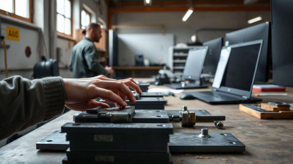
Once the design basis is understood, the detailer develops the physical steel model. Advance Steel is built around structural steel elements rather than only generic 3D geometry. Beams, columns, bracing, plates, stairs, railings, bolts, welds and connections can be represented as recognizable fabrication objects with associated data.
A typical steel connection detailing sequence is:
- Set the project environment, grids, levels, naming rules, drawing standards and relevant material information.
- Model primary members and secondary framing, checking orientation, end conditions and intersections.
- Apply suitable connection configurations for base plates, beam-to-column joints, bracing nodes, splices, end plates and other project-specific conditions.
- Add bolts, holes, plates, welds, stiffeners and other components needed to describe the physical connection.
- Review clearances, access for bolting and welding, erection sequence, transport limitations and interfaces with surrounding construction.
- Send non-standard or uncertain connections for engineering confirmation before issuing fabrication information.
Connection automation can accelerate repetitive work, but an automatically created connection is not automatically approved. Check bolt access, edge distances, plate thickness, weld visibility, member clashes, connection forces and the requirements of the responsible engineer. Pay particular attention to unusual nodes, sloping members, skewed framing and locations where architectural or MEP coordination restricts the available space.
Model discipline matters. Use consistent marks, naming, profiles, materials and revision information. Avoid representing fabrication-critical components as disconnected generic solids when the workflow needs them to appear in schedules, drawings or production exports. The more faithfully the model describes the intended fabrication, the less manual reconstruction is required later.
Producing steel fabrication shop drawings and documents
Fabrication documents should answer practical questions for the workshop: which parts belong together, what material and thickness are required, where are the holes and welds, how is the assembly oriented, and which revision is valid?
Common deliverables include:
- General arrangement drawings showing grids, levels, framing and erection references.
- Assembly or main-part drawings showing how individual components form a transportable or erectable unit.
- Single-part drawings for plates, beams, columns and other fabricated pieces.
- Sections and details for complex connections, joints and interfaces.
- Material lists, bolt lists, weld information and other schedules required by the shop.
- Revision records and issue information for design, fabrication and site coordination.
Advance Steel can keep the 3D model, fabrication drawings, material data and production outputs connected. That connection is valuable when a member changes: the detailer can identify affected views and regenerate documents rather than manually redrawing every representation. The documents still require checking. Automated drawing creation can place dimensions and labels, but it cannot judge every workshop preference, erection risk or project-specific presentation requirement.
Use a controlled checking process before issue. Compare drawing geometry with the model, confirm marks and revisions, inspect dimensions at connection interfaces, review material and bolt lists, and verify that details are legible at the printed or digital scale used by the workshop. A second person should review critical drawings where possible, especially for complex assemblies and high-consequence connections.
Creating and checking NC files for steel fabrication
NC files for steel fabrication translate model information into instructions or data that a compatible cutting, drilling or processing machine can use. They are not a substitute for shop drawings: the workshop may need both machine data and human-readable documentation.
The process normally includes:
- Confirm that the model contains complete profiles, plates, holes, cuts, notches, fittings and relevant part identifiers.
- Check that the export settings match the receiving workshop, machine format and project requirements.
- Generate NC output from the approved model revision.
- Review file names, part marks, quantities, orientation and associated drawings or lists.
- Run the receiving software or machine-side validation process where available.
- Resolve unsupported geometry, ambiguous cuts, missing holes or processing conflicts before release.
Machine compatibility must be checked rather than assumed. Different fabrication systems can interpret formats, tool paths, profiles and processing instructions differently. The detailer should confirm the required format with the workshop and test representative parts, including plates with holes, beams with cuts, sloped members and complex connection components.
NC output is only as reliable as the model and the post-processing configuration behind it. Keep the model revision, exported file set and issued drawings traceable. Do not overwrite approved files without a clear revision procedure. If the workshop reports a processing limitation, record the agreed correction in the model or project workflow instead of applying an isolated manual fix that will disappear during the next export.
Exchanging BIM data with Revit and other teams
BIM exchange for steel structures works best when teams agree on purpose and information requirements before exchanging files. A structural engineer may need analytical or design coordination information, while a fabricator needs accurate physical steel geometry, connection data and marks. These are related but not identical views of the project.
For an exchange with Revit or another BIM platform, clarify:
- Which software and file formats each team will use.
- Whether the exchange is for coordination, design review, quantity information or fabrication.
- Which elements are authoritative in each model.
- How coordinates, units, levels, grids and object names will be maintained.
- How often models will be exchanged and how revisions will be identified.
- Which properties must be transferred, and which fabrication details remain in the detailing model.
Revit is useful for coordinated building information and communication between structural, architectural and MEP teams. Advance Steel is more focused on structural steel detailing and fabrication information. Depending on the project, the detailer may receive a Revit model for coordination, develop the steel detailing model in Advance Steel, and return suitable coordination information without expecting the building model to contain every workshop-level detail.
After an import or export, inspect the result rather than relying on a successful file transfer message. Check member placement, elevations, orientation, profiles, openings, connection zones and interfaces with concrete or other trades. Use visual comparison and model review procedures to distinguish a genuine design change from an exchange or mapping issue.
Choosing the right Autodesk tools for your role
| Role or requirement | Suitable Autodesk tool | Proč se hodí | Důležité omezení |
|---|---|---|---|
| Steel detailer or fabricator | Advance Steel | Structural steel objects, connections, fabrication drawings, material information and production-oriented outputs in one detailing workflow. | Requires disciplined modelling, project standards and checking; it does not replace engineering approval. |
| Structural engineer | Robot Structural Analysis | Analytical modelling, structural evaluation, force paths, deflection, stability and code-check workflows. | An analytical model is not the same as a complete fabrication model. |
| Building project BIM team | Revit | Coordinated architectural, structural and MEP model information, views, sheets and schedules. | Detailed steel fabrication and machine output may require a dedicated steel detailing workflow. |
| 2D CAD documentation or legacy detail work | AutoCAD | Precise geometry, technical drawings, layouts and file-based CAD communication. | Manual 2D documentation does not provide the same connected model-to-fabrication workflow as specialized steel detailing. |
For a steel fabrication shop, Advance Steel is generally the most direct choice when the main requirement is to move from a structural steel model to coordinated shop drawings and production information. Robot Structural Analysis is more appropriate for the engineering analysis stage. Revit is a strong choice when the primary responsibility is building BIM coordination. AutoCAD remains useful for precise CAD documentation, supplementary details or workflows that are intentionally drawing-based.
Many projects use more than one of these tools. The important decision is not to force one application to perform every task, but to define the handoff between analysis, BIM coordination, detailing, documentation and fabrication. A clear exchange plan prevents duplicated modelling and helps each team work with the information it actually needs.
A practical release checklist
Before sending a model, drawing package or NC file to the workshop, verify the following:
- The issue corresponds to the approved design revision.
- Grid, level, coordinate and unit information is consistent.
- Member profiles, materials, marks and quantities are complete.
- Connections include the required plates, bolts, holes, welds and stiffeners.
- Critical clashes and fabrication or erection access issues have been reviewed.
- Shop drawings are readable and agree with the model.
- Schedules and lists match the drawing issue.
- NC files were generated from the same approved model revision.
- The receiving workshop has confirmed the expected file format and processing requirements.
- Open questions and assumptions are clearly recorded for the project team.
Genuine Autodesk licences, including Advance Steel, Revit, Robot Structural Analysis and AutoCAD, are available from KEYFORREST with instant electronic delivery. Check the current product page for the available licence term and software details.
Často kladené otázky
What is a steel detailing workflow?
It is the controlled process of converting structural design information into a detailed steel model, connection information, fabrication drawings, schedules and, where required, NC files for production.
Can Advance Steel create NC files?
Advance Steel supports production-oriented outputs from a structural steel model, including NC workflows where the project and receiving fabrication system are configured for them. Confirm the required format and machine compatibility with the workshop before release.
Is Revit enough for steel fabrication shop drawings?
Revit can support structural BIM coordination and documentation, but detailed steel fabrication often needs a specialized tool such as Advance Steel for connections, fabrication objects, shop drawings and production data.
Does steel detailing software replace structural engineering?
No. It documents and develops the physical detailing workflow, but the responsible engineer must define or approve the structural design, connection requirements and project-specific decisions.
Why do NC files and shop drawings both matter?
NC files provide machine-oriented production data, while shop drawings communicate assembly, orientation, dimensions, materials and installation information to people. They should be generated from and checked against the same approved model.

O autorovi Marios Chaidousis
Související příspěvky
Jak zabezpečit soubory projektu konstrukčního BIM
-
Publikoval: Marios Chaidousis
Konfliktní modely, zastaralé výkresy a nesledované výpočtové zprávy mohou způsobit vážná koordinační rizika. Tato příručka vysvětluje, jak mohou kanceláře konstrukčních inženýrů zabezpečit soubory projektů BIM pomocí řízeného přístupu, správy verzí a jasných postupů uvolňování.
Advance Steel nebo AutoCAD pro ocelové dílenské výkresy?
-
Publikoval: Marios Chaidousis
Správná volba závisí na tom, zda váš tým především vytváří pečlivě kontrolované výkresy, nebo potřebuje propojený ocelový model, který řídí detailování a výrobní informace. Toto srovnání se zaměřuje na skutečné úkoly v dílně a při detailování.
Jak vytvářet NC soubory v Autodesk Advance Steel
-
Publikoval: Marios Chaidousis
Spolehlivý export NC začíná koordinovaným modelem ocelové konstrukce, nikoli příkazem pro export. Tento postup kontroly kvality ukazuje, jak připravit data v Advance Steel, vytvářet výrobní soubory a před výrobou je porovnat s dílenskými výkresy.
Advance Steel vs Revit pro detailování ocelových konstrukcí
-
Publikoval: Marios Chaidousis
Advance Steel i Revit dokážou reprezentovat ocelové konstrukce, ale podporují různé fáze projektu. Toto srovnání vysvětluje, kam který nástroj zapadá a kdy je kombinovaný pracovní postup lepší volbou.

Autodesk Advance Steel pro výrobce ocelových konstrukcí
-
Publikoval: Marios Chaidousis
Autodesk Advance Steel propojuje modelování ocelových konstrukcí, návrh spojů, dílenské výkresy, materiálová data a výrobní výstupy v jediném pracovním postupu. Tato příručka vysvětluje, jak jej mohou výrobní a detailovací týmy využít od koordinace s projektantem až po přípravu v dílně.
Detekce kolizí v Revit MEP pro vzduchotechniku, potrubí a elektroinstalaci
-
Publikoval: Marios Chaidousis
Praktický kontrolní seznam pro detekci kolizí v Revit MEP, který pomáhá vyhledávat a řešit konflikty mezi vzduchotechnickým potrubím, instalacemi, elektroinstalací a prvky budovy. Naučte se připravit propojené modely, kontrolovat výsledky kolizí a zaznamenávat rozhodnutí pro výstavbu.
Pracovní postup Revit IFC pro architekty: průvodce koordinací
-
Publikoval: Marios Chaidousis
Spolehlivý pracovní postup Revit IFC pomáhá architektům vyměňovat užitečná otevřená BIM data s inženýry a současně zachovat nativní model Revit jako zdroj projektu. Tato příručka se věnuje přípravě, exportu, kontrole, koordinaci a správě verzí.

Od statického výpočtu k výkresům výztuže
-
Publikoval: Marios Chaidousis
Spolehlivý BIM pracovní postup pro železobetonové konstrukce není jen o přenosu sil mezi softwarem. Propojuje návrhové předpoklady, výsledky analýzy, inženýrská rozhodnutí, modely výztuže a výkresy připravené k vydání, přičemž odpovědnost zůstává na statikovi.

Plánování projektů pro kanceláře statiků
-
Publikoval: Marios Chaidousis
Harmonogram projektu statické kanceláře musí propojovat zaměření, výpočty, koordinaci, podrobné zpracování, kontroly a vydávání výkresů – nikoli pouze vyjmenovávat úkoly. Tento průvodce ukazuje, jak vytvořit praktický plán pomocí Microsoft Project Professional 2024.

Jak vytvářet profesionální statické výpočty
-
Publikoval: Marios Chaidousis
Opakovatelný pracovní postup pomáhá statikům převádět výsledky analýz do přehledných a snadno kontrolovatelných statických výpočtů. Kombinujte Autodesk Robot Structural Analysis s Word a Excel a dokumentujte předpoklady, kontroly, revize a schválení.
Vytváření PDF připravených pro stavební povolení z Revit a AutoCAD
-
Publikoval: Marios Chaidousis
Spolehlivý pracovní postup pro export architektonických výkresů do PDF není jen o exportu souboru. Připravte správně pohledy, výkresové listy a rozvržení a před vydáním PDF dokumentů pro stavební povolení nebo výběrová řízení zkontrolujte měřítko, tloušťky čar, pořadí stránek a úplnost dokumentace.

Pracovní postup Robot Structural Analysis Eurocode s Revit
-
Publikoval: Marios Chaidousis
Praktická příručka pro statické kanceláře používající Robot Structural Analysis a Revit při navrhování podle Eurokódů. Udržujte propojené předpoklady, rozhodnutí o ověření, analytické modely a BIM výstupy, aniž by se ztratil odborný úsudek inženýra.