
Blog
Revit MEP Clash Detection for HVAC, Plumbing and Electrical
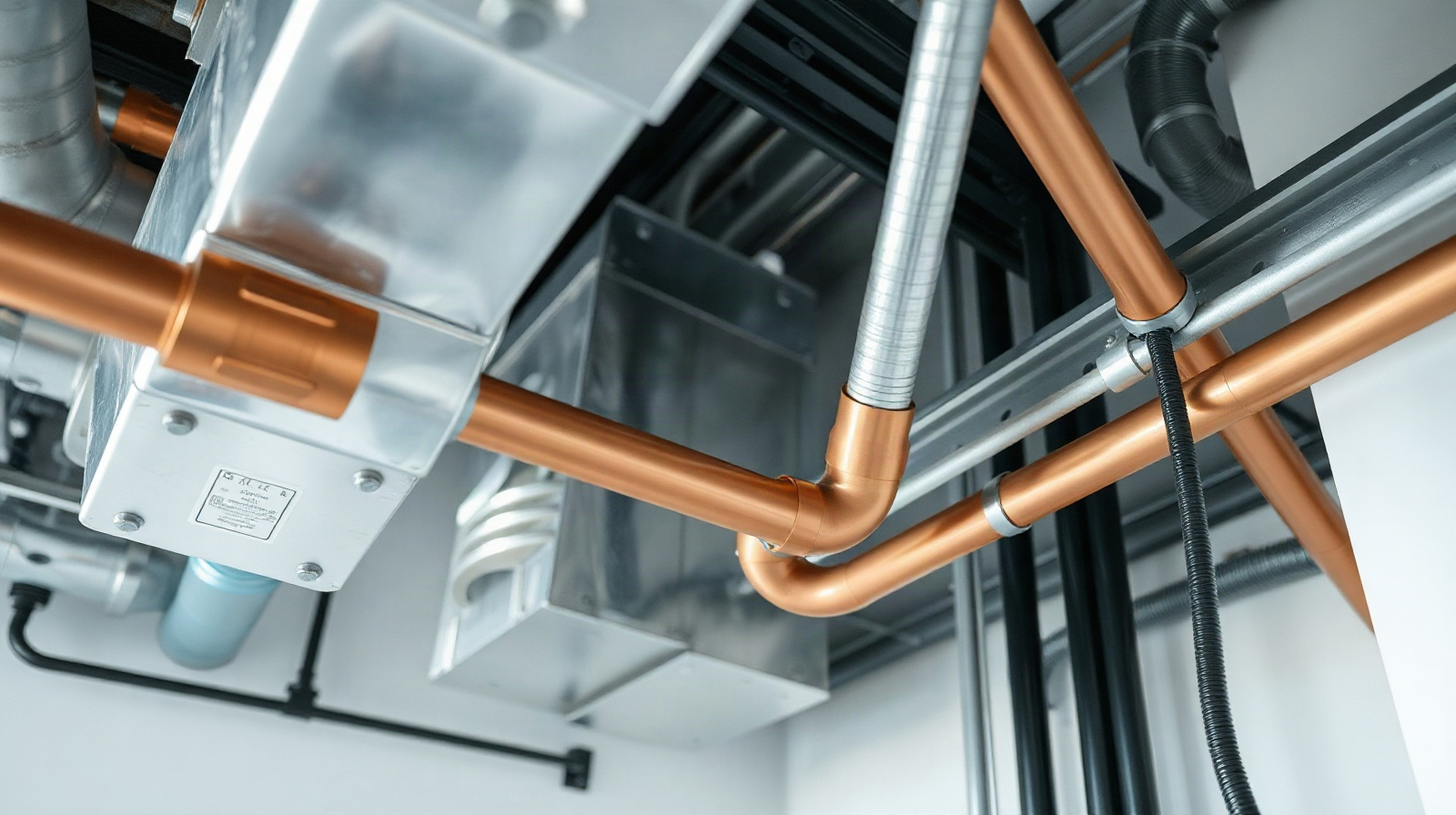
Revit MEP clash detection helps building services teams coordinate HVAC ductwork, pipes, plumbing equipment, cable trays, conduits and electrical equipment before these systems reach the construction site. The goal is not simply to produce a list of red markers in a model. Effective coordination protects maintenance access, preserves required routes and ceiling heights, supports fabrication-ready information and reduces changes during installation.
The most difficult areas are usually congested rather than large: suspended ceilings, vertical risers, plant rooms, service corridors and the zones around shafts, beams and structural openings. This checklist focuses on those areas and on a practical workflow for HVAC clash detection, plumbing and electrical coordination, and wider BIM coordination for MEP teams.
What clashes matter in MEP coordination
A geometric intersection is only one type of problem. Before running a check, agree what the project team considers a clash and which issues require action. A duct that passes through a pipe is an obvious hard clash, but a pipe may also be unacceptable if it blocks access to a valve or leaves no space for insulation.
Use the following categories when reviewing a coordinated model:
- Hard clashes: two physical elements occupy the same space, such as a duct crossing a beam, a pipe passing through a cable tray or equipment intersecting a wall.
- Clearance clashes: the elements do not touch, but the remaining space is insufficient for insulation, flanges, supports, access panels, fire stopping or installation tools.
- Access and maintenance clashes: a filter, valve, damper, cleanout, electrical panel or inspection hatch cannot be reached or removed safely.
- Route and height clashes: services fit geometrically but violate the agreed ceiling zone, corridor height, shaft allocation or required slope for drainage.
- Construction clashes: the route is possible in the design model but cannot be installed in a sensible sequence because supports, lifting paths or connection space are missing.
- Information clashes: a system has the wrong size, level, service classification, connection point or design status even though its geometry does not intersect another element.
Prioritise clashes by construction impact. A main supply duct intersecting a beam in a low ceiling usually deserves attention before a minor conduit crossing a small pipe. However, an apparently minor issue near a plant-room access door may have a major operational effect.
Preparing linked architectural and engineering models
Reliable MEP interference checking starts with reliable model setup. If the architectural, structural and services models use different coordinates, levels or phases, the clash results will contain noise and may hide genuine problems.
Confirm the coordination basis
Before checking geometry, confirm the project coordinate system, shared coordinates, units, levels, grids and model origin. Establish which model is authoritative for each element. For example, the architectural model may control room boundaries and ceiling layouts, while the structural model controls beams, slabs, columns and openings. The MEP model should not silently replace those references with locally redrawn geometry.
Load the right linked models
Link the current architectural and structural models into the MEP project and verify their positions visually in plan, section and 3D views. Use a controlled file-naming and revision process so that an old structural model is not used for a new coordination round. If multiple MEP disciplines are separate, link the HVAC, plumbing and electrical models or combine the services in an agreed coordination model.
Check more than one view. A riser may appear aligned in plan but be offset vertically. A duct may clear a beam in a floor plan but collide with the slab above. Sections through ceilings, shafts and plant rooms are particularly valuable because they reveal elevation and access problems that plan-only checks miss.
Clean the model before checking
Hide or exclude elements that are not relevant to the current check, such as temporary design geometry, duplicate links or obsolete options. Confirm that systems have sensible sizes and elevations. A placeholder duct with no insulation thickness can create a false sense of available space, while an incorrectly oversized pipe can generate a misleading priority.
Separate design status from coordination status. A route that is still being redesigned should not be treated as a final resolved route. Use the project team’s agreed worksharing, view and revision conventions so every participant can identify which geometry was checked.
Setting up checks for ducts, pipes and electrical systems
Revit provides model coordination tools, including interference checking, but the quality of the result depends on the elements and categories selected. Do not run one enormous test and assume that every meaningful issue has been found. Smaller, purposeful checks are easier to review and assign.
Build a clash matrix
Create a written matrix for the project. It should state which systems are checked against each other, who reviews the result and what rule applies. A typical matrix may include:
| Check | Typical reason | Review focus |
|---|---|---|
| HVAC ductwork against structure | Find beams, slabs, columns and walls blocking supply or return routes | Route, elevation, insulation, access and openings |
| Ductwork against pipes and electrical services | Coordinate congested ceiling zones and risers | Priority routes, service zones and installation sequence |
| Plumbing pipes against structure | Protect drainage slopes and penetration locations | Levels, falls, sleeves, fire stopping and cleanout access |
| Cable trays and conduits against ducts and pipes | Prevent service intersections and blocked cable routes | Tray access, bending space, support zones and separation |
| Equipment against architecture and structure | Confirm plant-room fit and connection space | Maintenance zones, doors, lifting routes and connections |
| MEP services against ceilings and access panels | Protect finished ceiling layouts and serviceability | Visible fixtures, hatch positions and ceiling height |
Check real system envelopes
Model the space that installation actually requires, not only the nominal centreline or physical core. For HVAC clash detection, include duct insulation where it affects the route. For plumbing, include pipe insulation and allow for fittings, valves, cleanouts and required slopes. For electrical layouts, consider the width and depth of trays, conduit bends, junction boxes and access to panels.
Do not use arbitrary clearance values as a substitute for project requirements. Clearance depends on the equipment, system, manufacturer information, fire strategy, acoustic requirements and construction method. Where the model does not contain the required clearance, record it as a coordination assumption and confirm it with the responsible engineer or project standard.
Use views that support review
Create dedicated coordination views for ceilings, risers, corridors and plant rooms. Apply clear colors for HVAC, plumbing, electrical and reference models. Sections and 3D views should be cropped to the problem area so the reviewer can understand the issue quickly. A useful view shows the intersecting elements, nearby structure, access zone and the proposed direction of change.
Run separate checks for high-risk zones rather than only by discipline. For example, review the entire ceiling void above a corridor, then the riser from each connected floor, then the plant room around each major item of equipment. This approach follows how installation decisions are made on site.

Reviewing, assigning and resolving clashes
A clash report is useful only when each result leads to a decision. Review results in a coordinated meeting or through the project’s issue-management process, and avoid changing every element simply because it is involved in an intersection.
Validate every result
Open the result in a focused 3D view and determine whether it is a real issue. Common false positives include duplicated linked geometry, elements that are intentionally embedded, temporary placeholders and intersections that occur outside the construction scope. A result may also be technically valid but already covered by an approved opening or sleeve.
For each valid issue, record the location, systems involved, responsible discipline, priority, proposed action and required due date. Add a screenshot or viewpoint when the issue is difficult to locate. The issue description should be specific: “Move the return duct 150 mm north to preserve valve access” is more useful than “MEP clash in Level 2 ceiling.”
Resolve by coordination priority
There is no universal rule that one discipline always moves. Use the agreed project hierarchy and consider gravity, slope, structural constraints, equipment connections and installation access. Drainage may need a continuous fall. A main duct may have limited route alternatives. A cable tray may be easier to reroute, but its bend radius and future cable capacity still matter.
A practical decision sequence is:
- Confirm whether the route, size and equipment selection are correct.
- Protect structural elements and required openings unless the structural team approves a change.
- Protect drainage slopes, major duct routes, plant connections and access zones.
- Adjust secondary services while preserving their support, separation and maintenance requirements.
- Check the revised route in plan, section and 3D, not only at the original clash point.
- Re-run the relevant check and close the issue only after the new geometry is verified.
Coordinate fabrication-ready information
Fabrication-ready models need more than visually clean routes. Confirm that fittings, connections, equipment clearances, supports and access requirements are represented at the level required by the project. A duct route that clears a beam may still be unsuitable if it leaves no room for a flange, hanger or installation joint. Likewise, a pipe route may need a different fitting arrangement to be manufactured or installed efficiently.
For cost estimation, use coordinated sizes, quantities and specifications rather than unverified temporary geometry. Revit schedules can support quantity review, but they do not replace a commercial check of the project scope, specification and procurement assumptions.
Recording coordination decisions for construction
Coordination decisions should remain visible after the meeting. Record the agreed route, the reason for the decision, the affected model elements and the model revision in the project’s issue register or common data environment. Keep unresolved items separate from approved deviations and design changes.
Before issuing coordinated information, complete a final checklist for each congested area:
- Architectural and structural links are the approved coordination revisions.
- Levels, coordinates, shafts, openings and ceiling zones are aligned.
- Ducts include the relevant insulation and connection space.
- Pipes include fittings, slopes, valves, cleanouts and access requirements.
- Electrical trays, conduits, panels and equipment have realistic access and bend space.
- Plant rooms have maintenance zones, delivery paths and connection clearances.
- Resolved clashes have been rechecked after changes.
- Open issues are clearly assigned and not presented as construction-ready information.
- Schedules, views, sheets and model geometry reflect the same approved design.
Revit is strong for maintaining connected design, documentation and building data in a shared BIM workflow. It does not automatically decide which route is buildable, whether a clearance is acceptable or who should change a system. Larger federated projects may also use a dedicated coordination platform for broader model aggregation and issue management, while Revit remains the place where the design elements and documentation are developed.
For most MEP teams, the best result comes from combining disciplined model setup, targeted interference checks and human review of access, installation and maintenance. That is the difference between finding intersections and achieving practical plumbing and electrical coordination.
Domande frequenti
What is Revit MEP clash detection?
It is the process of checking Revit building services models and linked architectural or structural models for intersections, insufficient clearances and coordination problems. It includes HVAC, plumbing, electrical and equipment reviews.
Can Revit find every MEP clash?
No. Automated checks are effective for many geometric intersections, but they do not reliably judge maintenance access, installation sequence, drainage requirements or every project-specific clearance. Human review remains necessary.
Which areas should be checked first?
Start with congested ceilings, vertical risers, plant rooms, service corridors, shafts and locations where ducts or pipes cross beams and slabs. These areas have the greatest risk of late redesign and difficult installation.
Should HVAC, plumbing and electrical models be checked separately?
Use separate discipline and category checks to keep results manageable, then review combined zones where services compete for the same space. Both approaches are needed for effective BIM coordination for MEP.
Which Autodesk product is suitable for MEP coordination?
Autodesk Revit is designed for coordinated BIM work across architecture, structural engineering and MEP. Firms needing a broader Autodesk building and construction toolset can also consider the Architecture, Engineering and Construction Collection. Genuine Autodesk licences are available from KEYFORREST with instant electronic delivery; see the current product page for the available licence options.

Informazioni su Marios Chaidousis
Articoli correlati
Come proteggere i file dei progetti BIM strutturali
-
Pubblicato da Marios Chaidousis
Modelli in conflitto, disegni obsoleti e report di calcolo non tracciati possono creare seri rischi di coordinamento. Questa guida spiega come gli studi di ingegneria strutturale possono proteggere i file dei progetti BIM tramite accessi controllati, gestione delle versioni e procedure di rilascio chiare.

How to Create NC Files in Autodesk Advance Steel
-
Pubblicato da Marios Chaidousis
A reliable NC export starts with a coordinated steel model, not with the export command. This quality-control workflow shows how to prepare Advance Steel data, create fabrication files and compare them with shop drawings before production.

Advance Steel vs Revit for Steel Detailing
-
Pubblicato da Marios Chaidousis
Advance Steel and Revit can both represent structural steel, but they support different stages of a project. This comparison explains where each tool fits and when a combined workflow is the better choice.

Steel Detailing Workflow: Model to NC File
-
Pubblicato da Marios Chaidousis
A reliable steel detailing workflow connects engineering information to fabrication documents and machine-ready output. This guide follows the handoff from analysis and BIM coordination through connections, shop drawings and NC files.

Revit Electrical Layouts: A Practical MEP Workflow
-
Pubblicato da Marios Chaidousis
Revit electrical layouts work best as part of a coordinated MEP model rather than as isolated 2D drawings. This practical workflow covers setup, lighting and power, coordination, documentation and delivery checks.

How to Create Fabrication-Ready Ductwork in CAMduct
-
Pubblicato da Marios Chaidousis
A fabrication-ready duct model is more than a coordinated 3D layout. This workflow explains how to move controlled MEP information into CAMduct, validate it and prepare practical cutting and manufacturing outputs.

Best BIM Software for MEP Engineers: An Autodesk Guide
-
Pubblicato da Marios Chaidousis
The best BIM software for MEP engineers depends on whether you are developing coordinated building-services models, producing 2D documentation or preparing fabrication information. This practical guide maps common HVAC, plumbing and electrical tasks to Revit, AutoCAD, CADmep and the AEC Collection.

Flusso di lavoro Revit IFC per architetti: guida al coordinamento
-
Pubblicato da Marios Chaidousis
Un flusso di lavoro Revit IFC affidabile aiuta gli architetti a scambiare dati BIM aperti utili con gli ingegneri, mantenendo il modello Revit nativo come fonte del progetto. Questa guida tratta preparazione, esportazione, verifica, coordinamento e controllo delle versioni.

From Structural Analysis to Reinforcement Drawings
-
Pubblicato da Marios Chaidousis
A reliable reinforced concrete BIM workflow does more than transfer forces between software. It connects design assumptions, analysis results, engineering decisions, reinforcement models and issue-ready drawings while keeping responsibility with the engineer.

Creare PDF pronti per i permessi edilizi da Revit e AutoCAD
-
Pubblicato da Marios Chaidousis
Un flusso di lavoro affidabile per i PDF dei disegni architettonici non consiste solo nell'esportare un file. Prepara correttamente viste, tavole e layout, quindi verifica la scala, gli spessori delle linee, l'ordine delle pagine e la completezza del documento prima di emettere i documenti PDF per i permessi edilizi o le gare.

Robot Structural Analysis Eurocode Workflow with Revit
-
Pubblicato da Marios Chaidousis
A practical guide for structural offices using Robot Structural Analysis and Revit for Eurocode-based design. Keep assumptions, verification decisions, analytical models and BIM deliverables connected without hiding engineering judgement.

Best BIM Software for Structural Engineering Offices
-
Pubblicato da Marios Chaidousis
The best BIM software for structural engineers is usually a coordinated workflow rather than one application. This guide maps Revit, Robot Structural Analysis and Advance Steel to the daily work of a structural design office.